Dtc P0122 Throttle / Pedal Position Sensor / Switch A Circuit Low Input
DESCRIPTION
MONITOR DESCRIPTION
WIRING DIAGRAM
INSPECTION PROCEDURE
CHECK WIRE HARNESS (THROTTLE POSITION SENSOR - ECM)
CHECK ECM (VC VOLTAGE)
REPLACE DIESEL THROTTLE BODY ASSEMBLY (THROTTLE VALVE)
CHECK IF DTC OUTPUT RECURS (DTC P0120/41, P0122/41 AND/OR P0123/41)
DTC P0122 Throttle / Pedal Position Sensor / Switch "A" Circuit Low Input |
DTC P0123 Throttle / Pedal Position Sensor / Switch "A" Circuit High Input |
DESCRIPTION
- HINT:
- These troubleshooting procedures are for the throttle position sensor.
- This electrical throttle system does not use a throttle cable.
- This throttle valve position sensor is a non-contact type.
The throttle position sensor is mounted on the diesel throttle body and detects the opening angle of the throttle valve. This sensor is electronically controlled and uses Hall-effect elements.The ECM judges the vehicle's driving conditions from the signals input to its VLU terminal. The data is one of the conditions for EGR control, etc.DTC No.
| DTC Detection Condition
| Trouble Area
|
-
| Condition of DTC P0120/41, P0122/41 or P0123/41 continues for 5 seconds (open or short in throttle position sensor circuit)
| -
|
P0120/41
| Throttle position sensor output (VLU) flutters up and down beyond normal operating range
(less than 0.2 V or more than 4.8 V)
(1 trip detection logic)
| - Open or short in throttle valve position sensor circuit
- Throttle position sensor
- ECM
|
P0122/41
| Throttle position sensor output (VLU) is less than 0.2 V
(1 trip detection logic)
| - Throttle position sensor
- Open or short in VLU circuit
- Open in VC circuit
- ECM
|
P0123/41
| Throttle position sensor output (VLU) is more than 4.8 V
(1 trip detection logic)
| - Throttle position sensor
- Open in E2 circuit
- VC and VLU circuits are short-circuited
- ECM
|
MONITOR DESCRIPTION
When the output voltage of the throttle position sensor deviates from the normal operating range (between 0.2 V and 4.8 V) for more than 3 seconds, the ECM interprets this as a malfunction of the sensor circuit and illuminates the MIL.
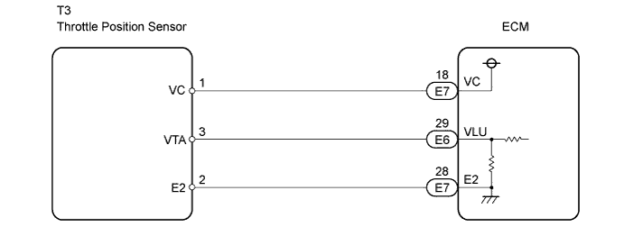
WIRING DIAGRAM
INSPECTION PROCEDURE
- HINT:
- If DTCs related to different systems that have terminal E2 as the ground terminal are output simultaneously, terminal E2 may have an open circuit.
- Read freeze frame data using the intelligent tester. Freeze frame data records the engine conditions when a malfunction is detected. When troubleshooting, freeze frame data can help determine if the vehicle was running or stopped, if the engine was warmed up or not, and other data from the time the malfunction occurred.
- NOTICE:
- If the ECM is replaced, the new ECM needs initialization (Toyota Fortuner RM0000012X2005X.html).
| 1.CHECK WIRE HARNESS (THROTTLE POSITION SENSOR - ECM) |
Disconnect the E6 and E7 ECM connectors.
Disconnect the T3 throttle position sensor connector.
Measure the resistance of the wire harness side connectors.
- Standard resistance:
Tester Connection
| Specified Condition
|
E7-18 (VC) - T3-1 (VC)
| Below 1 Ω
|
E6-29 (VLU) - T3-3 (VTA)
| Below 1 Ω
|
E7-28 (E2) - T3-2 (E2)
| Below 1 Ω
|
E7-18 (VC) or T3-1 (VC) - Body ground
| 10 kΩ or higher
|
E6-29 (VLU) or T3-3 (VTA) - Body ground
| 10 kΩ or higher
|
E7-28 (E2) or T3-2 (E2) - Body ground
| 10 kΩ or higher
|
| | REPAIR OR REPLACE HARNESS AND CONNECTOR |
|
|
Disconnect the T3 throttle position sensor connector.
Turn the ignition switch ON.
Measure the voltage of the ECM connector.
- Standard voltage:
Tester Connection
| Specified Condition
|
E7-18 (VC) - E7-28 (E2)
| 4.5 to 5.5 V
|
| 3.REPLACE DIESEL THROTTLE BODY ASSEMBLY (THROTTLE VALVE) |
| 4.CHECK IF DTC OUTPUT RECURS (DTC P0120/41, P0122/41 AND/OR P0123/41) |
Clear the DTC(s) (Toyota Fortuner RM0000012WY00LX.html).
Start the engine.
Idle the engine for 60 seconds, and repeat quick engine revving to 2,500 rpm for 30 seconds.
Read the DTC(s).
- Result:
Display (DTC Output)
| Proceed to
|
P0120/41, P0122/41 and/or P0123/41
| A
|
No output
| B
|