Dtc P0045/34 Turbocharger / Supercharger Boost Control Solenoid Circuit / Open
DESCRIPTION
MONITOR DESCRIPTION
WIRING DIAGRAM
INSPECTION PROCEDURE
INSPECT TURBOCHARGER SUB-ASSEMBLY (DC MOTOR)
INSPECT TURBO MOTOR DRIVER
CHECK WIRE HARNESS (TURBO MOTOR DRIVER - ECM)
CHECK WIRE HARNESS (TURBO MOTOR DRIVER - NOZZLE VANE POSITION SENSOR AND DC MOTOR)
DTC P0045/34 Turbocharger / Supercharger Boost Control Solenoid Circuit / Open |
DESCRIPTION
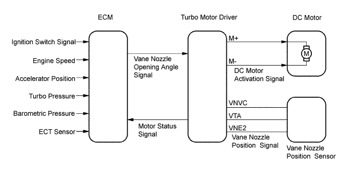
The turbocharger system is comprised of the Variable Nozzle (VN) type turbocharger, the turbo motor driver and ECM.The turbocharger has nozzle vane which opens and closes to control the volume of the exhaust gas flowing into the turbine. This, in turn, controls the boost pressure, when the nozzle vane moves towards the closing direction, the pressure increases. When the vane moves towards the opening direction, the pressure decreases. The turbocharger actuator built on the turbine side activates the nozzle vane. The nozzle vane position sensor built on the actuator detects the opening angle of nozzle vane. The nozzle vane position sensor signal is sent via the turbo motor driver to the ECM. Then, based on the signal, the ECM actuates the actuator. The ECM sends a target nozzle vane position signal to the turbo motor driver to obtain the nozzle vane position for the optimal boost pressure in accordance with the driving conditions.DTC No.
| DTC Detection Condition
| Trouble Area
|
P0045/34
| When either condition below is met:
- Open or short in turbo motor driver circuit continues for 0.5 seconds or more
- When communication error occurs between turbo motor and ECM
(1 trip detection logic)
| - Turbo motor driver
- Open or short in turbo motor driver circuit
- Turbocharger sub-assembly
- ECM
|
MONITOR DESCRIPTION
This DTC is detected 5 seconds after the ignition switch is turned ON.
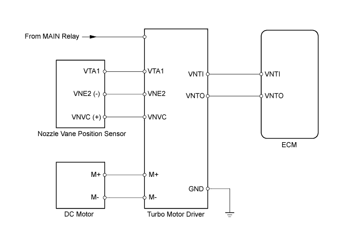
WIRING DIAGRAM
INSPECTION PROCEDURE
- HINT:
- Read freeze frame data using the intelligent tester. Freeze frame data records the engine conditions when a malfunction is detected. When troubleshooting, freeze frame data can help determine if the vehicle was running or stopped, if the engine was warmed up or not, and other data from the time the malfunction occurred.
- NOTICE:
- If the ECM is replaced, the new ECM needs initialization (Toyota Fortuner RM0000012X2005X.html).
| 1.INSPECT TURBOCHARGER SUB-ASSEMBLY (DC MOTOR) |
| | REPLACE TURBOCHARGER SUB-ASSEMBLY |
|
|
| 2.INSPECT TURBO MOTOR DRIVER |
| | REPLACE TURBO MOTOR DRIVER |
|
|
| 3.CHECK WIRE HARNESS (TURBO MOTOR DRIVER - ECM) |
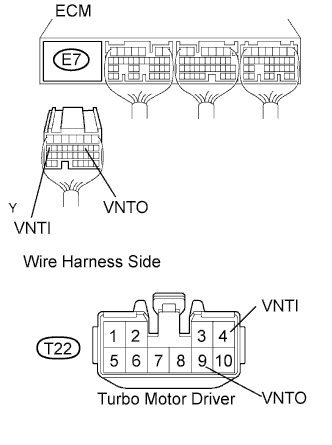
Disconnect the E7 ECM connector.
Disconnect the T22 turbo motor driver connector.
Measure the resistance of the wire harness side connectors.
- Standard resistance:
Tester Connection
| Specified Condition
|
E7-10 (VNTO) - T22-9 (VNTO)
| Below 1 Ω
|
E7-17 (VNTI) - T22-4 (VNTI)
| Below 1 Ω
|
E7-10 (VNTO) or T22-9 (VNTO) - Body ground
| 10 kΩ or higher
|
E7-17 (VNTI) or T22-4 (VNTI) - Body ground
| 10 kΩ or higher
|
| | REPAIR OR REPLACE HARNESS AND CONNECTOR |
|
|
| 4.CHECK WIRE HARNESS (TURBO MOTOR DRIVER - NOZZLE VANE POSITION SENSOR AND DC MOTOR) |
Disconnect the T22 turbo motor drive connector.
Disconnect the T11 nozzle vane position sensor connector.
Disconnect the T10 DC motor connector.
Measure the resistance of the wire harness side connectors.
- Standard resistance:
Tester Connection
| Specified Condition
|
T22-1 (VNVC) - T11-3 (VNVC)
| Below 1 Ω
|
T22-5 (VTA1) - T11-1 (VTA1)
| Below 1 Ω
|
T22-2 (VNE2) - T11-2 (VNE2)
| Below 1 Ω
|
T22-10 (M+) - T10-2 (M+)
| Below 1 Ω
|
T22-3 (M-) - T10-1 (M-)
| Below 1 Ω
|
T22-1 (VNVC) or T11-3 (VNVC) - Body ground
| 10 kΩ or higher
|
T22-5 (VTA1) or T11-1 (VTA1) - Body ground
| 10 kΩ or higher
|
T22-2 (VNE2) or T11-2 (VNE2) - Body ground
| 10 kΩ or higher
|
T22-10 (M+) or T10-2 (M+) - Body ground
| 10 kΩ or higher
|
T22-3 (M-) or T10-1 (M-) - Body ground
| 10 kΩ or higher
|
| | REPAIR OR REPLACE HARNESS AND CONNECTOR |
|
|