DESCRIPTION
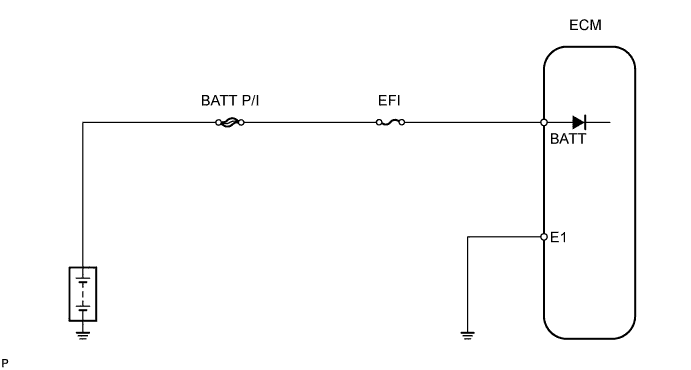
WIRING DIAGRAM
INSPECTION PROCEDURE
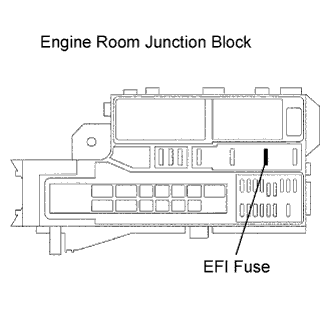
INSPECT FUSE (EFI)
CHECK ECM (BATT VOLTAGE)
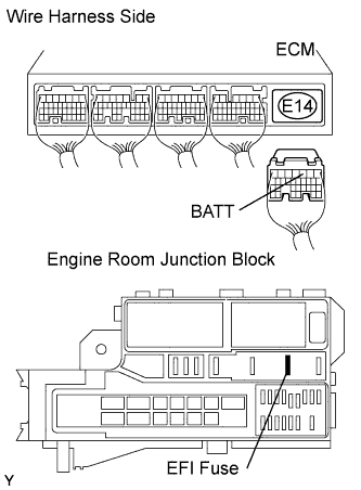
CHECK WIRE HARNESS (EFI FUSE - ECM AND BATTERY)
INSPECT BATTERY
DESCRIPTION
The battery supplies power to terminal BATT of the ECM even when the ignition switch is OFF. This power allows the ECM to store DTC history, freeze frame data, fuel trim values, and other data.DTC No.
| DTC Detection Condition
| Trouble Area
|
P0560
| Open in back-up power source circuit
| - Open in back-up power source circuit
- ECM
|
- HINT:
- If DTC P0560 is set, the ECM does not store other DTCs.
WIRING DIAGRAM
INSPECTION PROCEDURE
- HINT:
- Reed freeze frame data using the intelligent tester. Freeze frame data records the engine conditions when a malfunction is detected. when troubleshooting, freeze frame data can help determine if the vehicle was running or stopped, if the engine was warmed up or not, if the air-fuel ratio was lean or rich, and other data from the time the malfunction occurred.
Remove the EFI fuse from the engine room junction block.
Measure the resistance of the fuse.
- Standard resistance:
- Below 1 Ω
| | CHECK FOR SHORT IN ALL HARNESSES AND COMPONENTS CONNECTED FUSE |
|
|
| 2.CHECK ECM (BATT VOLTAGE) |
Measure the voltage of the ECM connectors.
- Standard voltage:
Tester Connection
| Specified Condition
|
E14-3 (BATT) - E17-1 (E1)
| 9 to 14 V
|
| 3.CHECK WIRE HARNESS (EFI FUSE - ECM AND BATTERY) |
Disconnect the E14 ECM connector.
Remove the EFI fuse from the engine room junction block.
Disconnect the cable from the positive (+) battery terminal.
Measure the resistance of the wire harness side connectors.
- Standard resistance:
Tester Connection
| Specified Condition
|
E14-3 (BATT) - Junction block EFI fuse terminal 2
| Below 1 Ω
|
Junction block EFI fuse terminal 1 - Positive (+) battery cable
| Below 1 Ω
|
E14-3 (BATT) or Junction block EFI fuse terminal 2 - Body ground
| 10 kΩ or higher
|
Junction block EFI fuse terminal 1 or Positive (+) battery cable - Body ground
| 10 kΩ or higher
|
| | REPAIR OR REPLACE HARNESS AND CONNECTOR |
|
|
Check that the battery is not depleted.
- OK:
- Battery is not depleted.
| | REPLACE OR RECHARGE BATTERY |
|
|
| OK |
|
|
|
| CHECK AND REPLACE ENGINE ROOM RELAY BLOCK |
|