Dtc P0504 Brake Switch A / B Correlation
DESCRIPTION
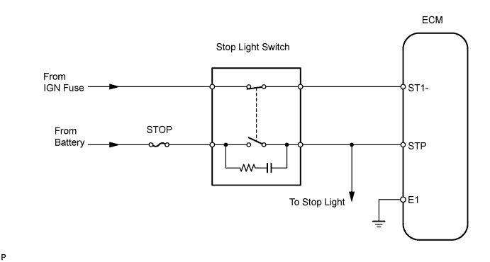
WIRING DIAGRAM
INSPECTION PROCEDURE
CHECK OPERATION OF STOP LIGHT
INSPECT STOP LIGHT SWITCH
READ VALUE USING INTELLIGENT TESTER (STP SIGNAL, ST1- VOLTAGE)
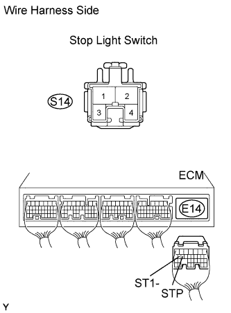
CHECK WIRE HARNESS (STOP LIGHT SWITCH - ECM)
DTC P0504 Brake Switch "A" / "B" Correlation |
DESCRIPTION
In this system, the signal of the stop light switch is used to judge whether the acceleration system is abnormal or not.The stop light switch has a duplex system (signals STP and ST1-) to memorize the abnormality when the signals of depressing and releasing the brake pedal are detected simultaneously.- HINT:
- The Normal condition is shown in the table below.
Signal
| Brake Pedal Released
| In Transition
| Brake Pedal Depressed
|
STP
| OFF
| ON
| ON
|
ST1-
| ON
| ON
| OFF
|
DTC No.
| DTC Detection Condition
| Trouble Area
|
P0504
| - Conditions (a), (b) and (c) continue for 0.5 sec or more:
- (a) Ignition switch ON
- (b) Brake pedal released
- (c) STP signal is OFF when ST1- signal is OFF
| - Short in stop light switch signal circuit
- STOP fuse
- Stop light switch
- ECM
|
WIRING DIAGRAM
INSPECTION PROCEDURE
- HINT:
- Read freeze frame data using the intelligent tester. Freeze frame data records the engine conditions when a malfunction is detected. When troubleshooting, freeze frame data can help determine if the vehicle was running or stopped, if the engine was warmed up or not, if the air-fuel ratio was lean or rich, and other data from the time the malfunction occurred.
| 1.CHECK OPERATION OF STOP LIGHT |
Check if the stop lights illuminate and turn off normally when the brake pedal is depressed and released.
- OK:
- Stop lights illuminate and turn off.
| | REPAIR OR REPLACE STOP LIGHT SWITCH CIRCUIT |
|
|
| 2.INSPECT STOP LIGHT SWITCH |
Measure the resistance of the switch.
- Standard resistance:
Tester Connection
| Condition
| Specified Condition
|
1 - 2
| Switch pin not pushed
| Below 1 Ω
|
3 - 4
| Switch pin not pushed
| 10 kΩ or higher
|
1 - 2
| Switch pin pushed
| 10 kΩ or higher
|
3 - 4
| Switch pin pushed
| Below 1 Ω
|
| | REPLACE STOP LIGHT SWITCH |
|
|
| 3.READ VALUE USING INTELLIGENT TESTER (STP SIGNAL, ST1- VOLTAGE) |
Connect the intelligent tester to the DLC3.
Turn the ignition switch ON and turn the tester ON.
Enter the following menus: Powertrain / Engine and ECT / Data List / Stop Light SW.
Check the result.
- OK:
Brake Pedal
| Specified Condition
|
Depressed
| STP signal ON
|
Released
| STP signal OFF
|
Measure the voltage of the E14 and E17 ECM connectors.
- Standard voltage:
Tester Connection
| Brake Pedal
| Specified Condition
|
E14-16 (ST1-) - E17-1 (E1)
| Depressed
| Below 1.5 V
|
E14-16 (ST1-) - E17-1 (E1)
| Released
| 7.5 to 14 V
|
| | CHECK FOR INTERMITTENT PROBLEMS |
|
|
| 4.CHECK WIRE HARNESS (STOP LIGHT SWITCH - ECM) |
Disconnect the S14 stop light switch connector.
Disconnect the E14 ECM connector.
Measure the resistance of the wire harness side connectors.
- Standard resistance:
Tester Connection
| Specified Condition
|
S14-1 - E14-15 (STP)
| Below 1 Ω
|
S14-4 - E14-16 (ST1-)
| Below 1 Ω
|
S14-1 or E14-15 (STP) - Body ground
| 10 kΩ or higher
|
S14-4 or E14-16 (ST1-) - Body ground
| 10 kΩ or higher
|
| | REPAIR OR REPLACE HARNESS AND CONNECTOR |
|
|