READ VALUE OF INTELLIGENT TESTER (ACCEL POS #1 AND ACCEL POS #2)
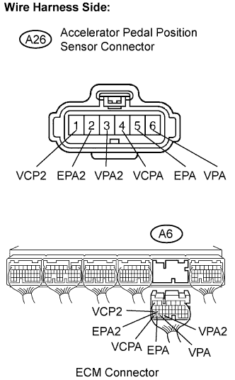
CHECK HARNESS AND CONNECTOR (ACCELERATOR PEDAL POSITION SENSOR - ECM)
REPLACE ACCELERATOR PEDAL ROD ASSEMBLY
CHECK WHETHER DTC OUTPUT RECURS (ACCELERATOR PEDAL POSITION SENSOR DTCS)
DTC P2121 Throttle / Pedal Position Sensor / Switch "D" Circuit Range / Performance
Description
HINT:
Refer to DTC P2120 .
| DTC No. | DTC Detection Condition | Trouble Area |
| P2121 | Difference between VPA and VPA2 less than 0.4 V, or more than 1.2 V for 0.5 seconds (1 trip detection logic) |
|
FAIL-SAFE
The accelerator pedal position sensor has two (main and sub) sensor circuits. If a malfunction occurs in either of the sensor circuits, the ECM detects the abnormal signal voltage difference between the two sensor circuits and switches to limp mode. In limp mode, the functioning circuit is used to calculate the accelerator pedal opening angle to allow the vehicle to continue driving. If both circuits malfunction, the ECM regards the opening angle of the accelerator pedal as being fully closed. In this case, the throttle valve remains closed as if the engine is idling. If a pass condition is detected and then the engine switch is turned to off, the fail-safe operation stops and the system returns to a normal condition.
Wiring diagram
Refer to DTC P2120.
Inspection procedure
HINT:
- Read freeze frame data using the intelligent tester. Freeze frame data records the engine conditions when malfunctions are detected. When troubleshooting, freeze frame data can help determine if the vehicle was moving or stationary, if the engine was warmed up or not, if the air-fuel ratio was lean or rich, and other data from the time the malfunction occurred .
- This DTC relates to the Accelerator Pedal Position (APP) sensor.
| 1.READ VALUE OF INTELLIGENT TESTER (ACCEL POS #1 AND ACCEL POS #2) |

-
Connect the intelligent tester to the DLC3.
-
Turn the engine switch on (IG) and turn the tester ON.
-
Enter the following menus: Power train / Engine / Data List / Accelerator Position No. 1 and Accelerator Position No. 2.
-
Read the values displayed on the tester.
Standard voltage:
Accelerator Pedal Operations ACCEL POS #1
(AP#1)ACCEL POS #2
(AP#2)Released 0.5 to 1.1 V 1.2 to 2.0 V Depressed 2.6 to 4.5 V 3.4 to 5.0 V
|
|
||||
| NG | |
| 2.CHECK HARNESS AND CONNECTOR (ACCELERATOR PEDAL POSITION SENSOR - ECM) |
-
Disconnect the A26 Accelerator Pedal Position (APP) sensor connector.
-
Disconnect the A6 ECM connector.
-
Measure the resistance of the wire harness side connector.
Standard resistance (Check for open):
Tester Connection Specified Condition VPA (A26-6) - VPA (A6-33) Below 1 ? EPA (A26-5) - EPA (A6-34) Below 1 ? VCPA (A26-4) - VCPA (A6-35) Below 1 ? VPA2 (A26-3) - VPA2 (A6-32) Below 1 ? EPA2 (A26-2) - EPA2 (A6-26) Below 1 ? VCP2 (A26-1) - VCP2 (A6-27) Below 1 ? Standard resistance (Check for short):
Tester Connection Specified Condition VPA (A26-6) or VPA (A6-33) - body ground 10 k? or higher EPA (A26-5) or EPA (A6-34) - body ground 10 k? or higher VCPA (A26-4) or VCPA (A6-35) - body ground 10 k? or higher VPA2 (A26-3) or VPA2 (A6-32) - body ground 10 k? or higher EPA2 (A26-2) or EPA2 (A6-26) - body ground 10 k? or higher VCP2 (A26-1) or VCP2 (A6-27) - body ground 10 k? or higher
-
Reconnect the APP sensor connector.
-
Reconnect the ECM connector.
|
|
||||
| OK | |
| 3.REPLACE ACCELERATOR PEDAL ROD ASSEMBLY |
| NEXT | |
| 4.CHECK WHETHER DTC OUTPUT RECURS (ACCELERATOR PEDAL POSITION SENSOR DTCS) |
-
Connect the intelligent tester to the DLC3.
-
Turn the engine switch on (IG) and turn the tester ON.
-
Clear DTCs .
-
Start the engine.
-
Allow the engine to idle for 15 seconds.
-
Enter the following menus: Power train / Engine / DTC.
-
Read DTCs.
Result:
Display (DTC Output) Proceed to P2121 A No output B
|
|
||||
| A | ||
|
||