Skid Control Buzzer Circuit
DESCRIPTION
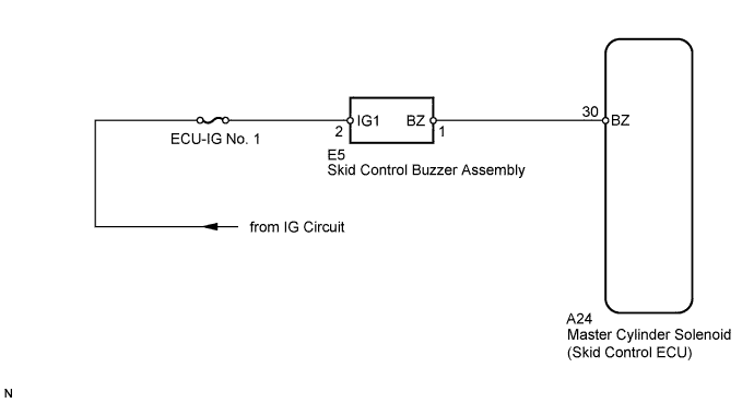
WIRING DIAGRAM
INSPECTION PROCEDURE
PERFORM ACTIVE TEST USING INTELLIGENT TESTER (BUZZER)
INSPECT SKID CONTROL BUZZER (POWER SOURCE TERMINAL)
INSPECT SKID CONTROL BUZZER
CHECK HARNESS AND CONNECTOR (SKID CONTROL BUZZER - SKID CONTROL ECU)
Description
The skid control buzzer sounds while the accumulator pressure is abnormally low or an abnormality causing low fluid pressure occurs.
Wiring diagram
Inspection procedure
NOTICE:
When replacing the master cylinder solenoid, perform zero point calibration .
| 1.PERFORM ACTIVE TEST USING INTELLIGENT TESTER (BUZZER) |
-
Connect the intelligent tester to the DLC3.
-
Turn the ignition switch to ON and turn the intelligent tester on.
-
Enter the following menus: Chassis / ABS/VSC/TRC / Active Test.
ABS/VSC/TRC
| Tester Display |
Test Part |
Control Range |
Diagnostic Note |
| Buzzer |
Skid control buzzer |
Buzzer ON/OFF |
The buzzer can be heard. |
-
Check that the buzzer sounds/stops when turning the skid control buzzer on/off by using the intelligent tester.
Result
| Result |
Proceed to |
| Buzzer sounds/stops |
A |
| Buzzer does not sound or sounds constantly |
B |
|
|
| USE SIMULATION METHOD TO CHECK |
|
| |
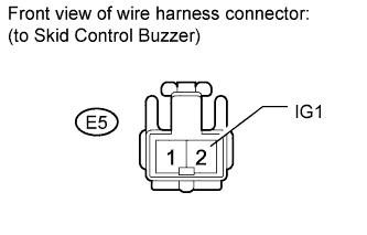
| 2.INSPECT SKID CONTROL BUZZER (POWER SOURCE TERMINAL) |
-
Disconnect the E5 skid control buzzer connector.
-
Measure the voltage according to the value(s) in the table below.
Standard Voltage:
| Tester Connection |
Switch Condition |
Specified Condition |
| E5-2 (IG1) - Body ground |
Ignition switch ON |
11 to 14 V |
|
|
| REPAIR OR REPLACE HARNESS OR CONNECTOR |
|
| |
| 3.INSPECT SKID CONTROL BUZZER |

-
Apply battery voltage to the skid control buzzer, and check that the buzzer sounds.
OK:
| Measurement Condition |
Specified Condition |
| Battery positive (+) voltage - Terminal 2 (IG1) |
Skid control buzzer sounds. |
| Battery negative (-) voltage - Terminal 1 (BZ) |
|
|
| REPLACE SKID CONTROL BUZZER ASSEMBLY |
|
| |
| 4.CHECK HARNESS AND CONNECTOR (SKID CONTROL BUZZER - SKID CONTROL ECU) |

-
Disconnect the A24 skid control ECU connector.
-
Measure the resistance according to the value(s) in the table below.
Standard Resistance:
| Tester Connection |
Condition |
Specified Condition |
| A24-30 (BZ) - E5-1 (BZ) |
Always |
Below 1 ? |
| A24-30 (BZ) - Body ground |
Always |
10 k? or higher |
Result
| Result |
Proceed to |
| NG |
A |
| OK |
LHD |
B |
| RHD |
C |
|
|
| REPLACE MASTER CYLINDER SOLENOID |
|
| |
|
|
| REPLACE MASTER CYLINDER SOLENOID |
|
| |
| A |
|
| |
|
| REPAIR OR REPLACE HARNESS OR CONNECTOR |
|