1. DISCHARGE FUEL SYSTEM PRESSURE
-
Discharge the fuel system pressure.
2. PRECAUTION
NOTICE:
After turning the ignition switch off, waiting time may be required before disconnecting the cable from the battery terminal. Therefore, make sure to read the disconnecting the cable from the battery terminal notice before proceeding with work.
3. DISCONNECT CABLE FROM NEGATIVE BATTERY TERMINAL
NOTICE:
When disconnecting the cable, some systems need to be initialized after the cable is reconnected.
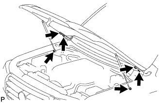
4. REMOVE HOOD SUB-ASSEMBLY
-
Remove the 2 hood support bolts and disconnect the hood supports.
-
Remove the 4 bolts and hood.
5. REMOVE COWL TOP VENTILATOR LOUVER SUB-ASSEMBLY
-
Remove the cowl top ventilator louver.
6. REMOVE RADIATOR ASSEMBLY
-
Remove the radiator assembly.
7. DRAIN ENGINE OIL
-
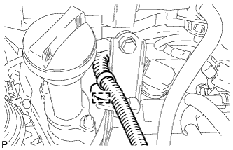
Remove the oil filler cap.
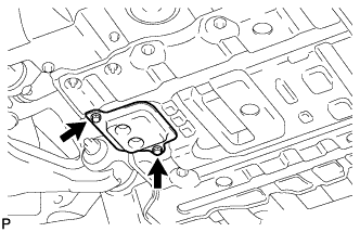
-
Remove the 2 bolts and service hole cover from the No. 2 engine under cover.
-
Remove the oil drain plug, and drain the engine oil from the oil pan.
NOTICE:
Collect the oil in an oil disposal container.
-
Wipe the oil pan and drain plug.
-
Install a new gasket and the drain plug.
Torque:
40 N*m{ 408 kgf*cm , 30 ft.*lbf }
8. REMOVE NO. 2 ENGINE UNDER COVER
9. REMOVE NO. 2 AIR CLEANER HOSE
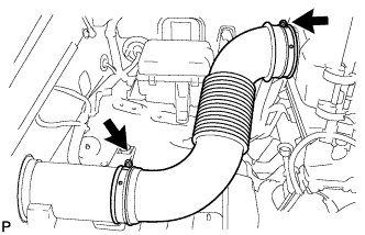
-
Loosen the 2 hose clamps and remove the air cleaner hose.
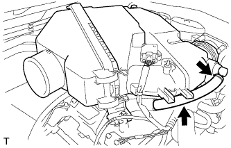
10. REMOVE AIR CLEANER ASSEMBLY
-
Disconnect the No. 2 ventilation hose.
-
Detach the hose clamp.
-
Disconnect the vacuum hose.
-
Disconnect the MAF meter connector.
-
Using a clip remover, detach the 2 wire harness clamps.
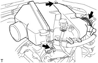
-
Loosen the hose clamp.
-
Remove the 2 bolts and air cleaner assembly.
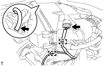
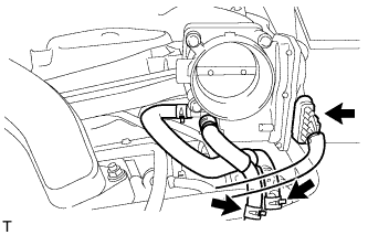
11. REMOVE INTAKE AIR SURGE TANK
-
Disconnect the throttle body connector.
-
Disconnect the No. 4 water by-pass hose.
-
Disconnect the No. 5 water by-pass hose.
-
Disconnect the purge line hose.
-
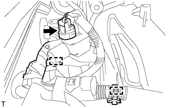
Disconnect the purge VSV connector.
-
Disconnect the No. 1 ventilation hose.
-
Disconnect the vacuum switching valve (for ACIS) connector.
-
Using a clip remover, detach the 2 wire harness clamps.
-
Remove the 2 bolts and throttle body bracket.
-
Using a clip remover, detach the wire harness clamp.
-
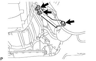
Remove the bolt and bracket from the No. 1 surge tank stay.
-
Remove the bolt and oil baffle plate.
-
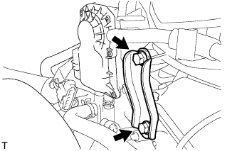
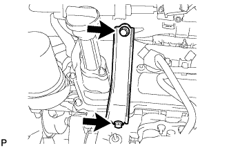
Remove the 2 bolts and No. 1 surge tank stay.
-
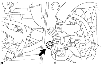
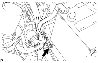
for Manual Transmission:
-
Remove the nut.
-
-
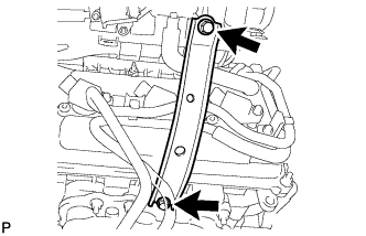
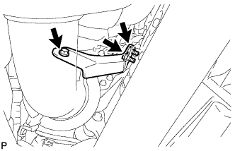
Remove the 2 bolts and No. 2 surge tank stay.
-
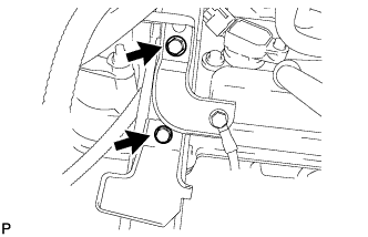
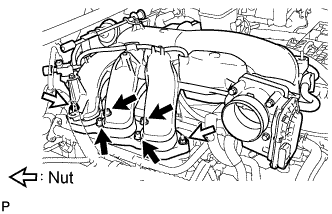
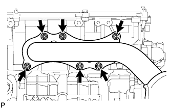
Remove the 2 nuts.
-
Using an 8 mm hexagon wrench, remove the 4 bolts. Then remove the intake air surge tank and gasket.
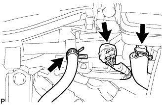
12. DISCONNECT ENGINE WIRE

-
Disconnect the ECM connector.
-
Remove the junction block cover.
-
Disconnect the 4 connectors from the junction block.
-
Using a clip remover, detach the 2 wire harness clamps and wire harness.
-
Remove the bolt and ground cables.
-
Remove the engine room relay block cover.
-
Disconnect the 2 connectors from the engine room relay block.
-
Remove the nut from the engine room relay block, and disconnect the No. 2 engine wire cover.
-
Detach the wire harness from the clamp.
-
Disconnect the connector, and using a clip remover, detach the engine wire to wire connector clamp from the engine room relay block.
-
Detach the wire harness from the body.
-
Detach the wire harness clamp from the hose.
-
Pull off the battery positive cable cover, and then remove the nut and battery positive cable.
-
Remove the bolt and ground cable and detach the wire harness clamp.
-
w/ Winch: Remove the 2 bolts and winch ground wire.
13. REMOVE FRONT NO. 2 EXHAUST PIPE ASSEMBLY
-
Disconnect the heated oxygen sensor connector.
-
Remove the 2 nuts and front exhaust pipe.
-
Remove the gasket from the front exhaust pipe.
14. REMOVE FRONT EXHAUST PIPE ASSEMBLY
-
Disconnect the heated oxygen sensor connector.
-
Remove the 2 nuts and front exhaust pipe.
-
Remove the gasket from the front exhaust pipe.
15. REMOVE FRONT FENDER APRON SEAL LH
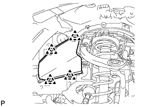
-
Using a clip remover, remove the 4 clips and fender apron seal.
16. REMOVE FRONT FENDER APRON SEAL REAR LH
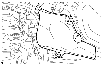
-
Using a clip remover, remove the 4 clips and fender apron seal.
17. REMOVE FRONT FENDER APRON SEAL FRONT RH
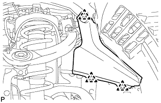
-
Using a clip remover, remove the 3 clips and fender apron seal.
18. REMOVE FRONT FENDER APRON SEAL REAR RH
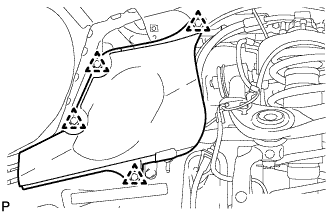
-
Using a clip remover, remove the 4 clips and fender apron seal.
19. REMOVE MANIFOLD STAY
-
Remove the 3 bolts and No. 1 manifold stay.
20. REMOVE EXHAUST MANIFOLD SUB-ASSEMBLY RH
-
Disconnect the air fuel ratio sensor connector.

-
Remove the 6 nuts, exhaust manifold and gasket from the cylinder head RH.
21. REMOVE NO. 2 MANIFOLD STAY
-
Remove the 3 bolts and No. 2 manifold stay.
22. REMOVE EXHAUST MANIFOLD SUB-ASSEMBLY LH
-
Disconnect the air fuel ratio sensor connector.
-
Remove the 6 nuts, exhaust manifold and gasket from the cylinder head LH.
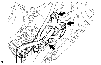
23. DISCONNECT WATER HOSE SUB-ASSEMBLY

-
Disconnect the water hoses.
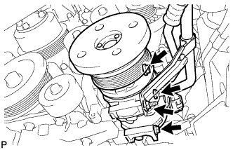
24. DISCONNECT VANE PUMP ASSEMBLY

-
Disconnect the power steering oil pressure switch connector.
-
Remove the 2 bolts, and disconnect the vane pump.
NOTICE:
Do not hit other parts with the pulley when disconnecting the vane pump.
HINT:
Make sure to suspend the vane pump securely.
25. REMOVE BATTERY
26. REMOVE GENERATOR ASSEMBLY
-
Remove the nut and disconnect the wire harness clamp bracket.
-
Disconnect the generator connector.
-
Remove the terminal cap.
-
Remove the nut and disconnect the generator wire.
-
Remove the wire harness clamp.
-
Remove the bolt and disconnect the wire harness clamp bracket.

-
Remove the 2 bolts and generator.
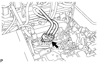
27. DISCONNECT COOLER COMPRESSOR ASSEMBLY
-
Disconnect the cooler compressor connector.
-
Remove the nut, 3 bolts and stud bolt, and disconnect the cooler compressor.
28. DISCONNECT NO. 1 AND NO. 2 FUEL PIPES
-
Disconnect the No. 1 and No. 2 fuel pipe.
-
Remove the fuel pipe clamp from the fuel tube connector.
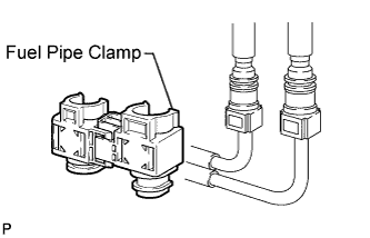
HINT:
Check for dirt or mud on the pipe and around the connector before disconnecting it. Clean if necessary.
-
Pinch the connector and disconnect the connector and pipe.
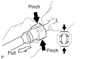
HINT:
If the connector and the pipe are stuck together, pinch the connector, push and pull the pipe to disconnect the pipe and pull it out.
NOTICE:
Do not use any tools.
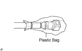
-
Check for dirt or mud on the seal surface of the disconnected pipe. Clean if necessary.
-
To protect the disconnected pipe and connector from damage and contamination, cover it with a plastic bag.
-
29. REMOVE MANUAL TRANSMISSION ASSEMBLY (for Manual Transmission)
-
Remove the manual transmission from the vehicle.
30. REMOVE AUTOMATIC TRANSMISSION ASSEMBLY (for Automatic Transmission)
-
Remove the automatic transmission from the vehicle.
31. REMOVE REAR NO. 1 ENGINE MOUNTING INSULATOR
HINT:
Only perform this procedure when replacement of the engine mounting insulator is necessary.

-
Remove the 4 bolts and rear engine mounting insulator from the transmission.
32. DISCONNECT NO. 1 OIL COOLER HOSE TUBE SUB-ASSEMBLY (for Automatic Transmission)

-
Remove the 2 bolts and cooler hose tube.
33. REMOVE CLUTCH COVER ASSEMBLY (for Manual Transmission)
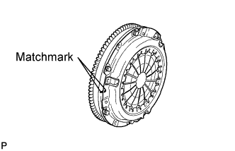
-
Put matchmarks on the clutch cover and flywheel.
-
Loosen each set bolt one turn at a time until spring tension is released.
-
Remove the 6 set bolts, and pull off the clutch cover.
NOTICE:
Do not drop the clutch disc.
34. REMOVE CLUTCH DISC ASSEMBLY (for Manual Transmission)
NOTICE:
Keep the lining part of the clutch disc, pressure plate and surface of the flywheel away from oil and foreign matter.
35. REMOVE FLYWHEEL SUB-ASSEMBLY (for Manual Transmission)
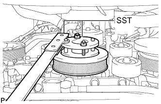
-
Using SST, hold the crankshaft.
SST
09213-54015 (91651-60855) 09330-00021
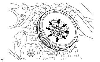
-
Remove the 8 bolts and flywheel.
NOTICE:
Do not reuse the bolts.
36. REMOVE DRIVE PLATE AND RING GEAR SUB-ASSEMBLY (for Automatic Transmission)
-
Using SST, hold the crankshaft.
SST
09213-54015 (91651-60855) 09330-00021

-
Remove the 8 bolts, rear spacer, drive plate and front spacer.
NOTICE:
Do not reuse the bolts.
37. REMOVE ENGINE ASSEMBLY

-
Install 2 engine hangers with 4 bolts as shown in the illustration.
Part No. Item Part No. No. 1 engine hanger 12281-31070 No. 2 engine hanger 12282-31050 Bolt 90119-08A87 Torque:
33 N*m{ 336 kgf*cm , 24 ft.*lbf }
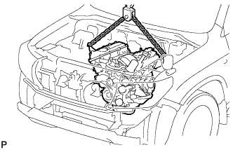
-
Attach an engine sling device and hang a engine with a chain block.

-
Remove the 2 nuts and 4 bolts from the front engine mounting insulator LH and RH.
-
Lift the engine out of the vehicle carefully.
NOTICE:
Make sure the engine is clear of all wiring and hoses.
-
Remove the front engine mounting insulator LH and RH.
-
Place the engine onto a working bench.
38. INSTALL ENGINE STAND
-
Install the engine onto an engine stand with bolts.
39. REMOVE ENGINE HANGER
-
Remove the 4 bolts and 2 engine hangers.