Lighting System - Turn Signal Light Circuit
DESCRIPTION
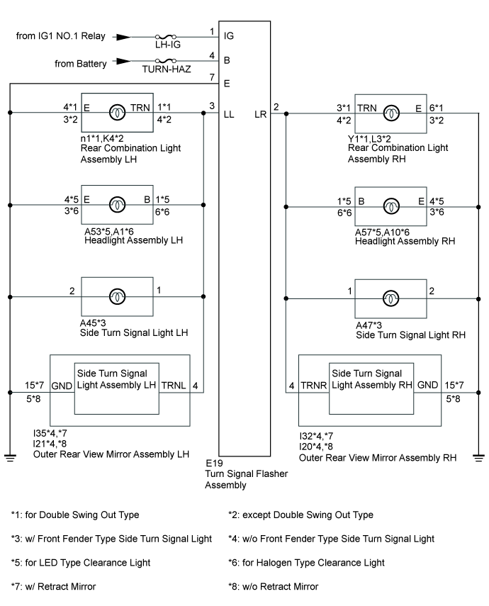
WIRING DIAGRAM
INSPECTION PROCEDURE
CHECK TURN SIGNAL LIGHT FUNCTION
CHECK HARNESS AND CONNECTOR (TURN SIGNAL FLASHER ASSEMBLY - BATTERY AND BODY GROUND)
CHECK HARNESS AND CONNECTOR (REAR COMBINATION LIGHT ASSEMBLY LH - TURN SIGNAL FLASHER ASSEMBLY AND BODY GROUND)
CHECK HARNESS AND CONNECTOR (REAR COMBINATION LIGHT ASSEMBLY RH - TURN SIGNAL FLASHER ASSEMBLY AND BODY GROUND)
LIGHTING SYSTEM - Turn Signal Light Circuit
DESCRIPTION
The turn signal flasher receives a turn signal switch signal from the headlight dimmer switch, and illuminates the front turn signal light, side turn signal light and rear turn signal light.
WIRING DIAGRAM
INSPECTION PROCEDURE
- Inspect the fuses and bulbs for circuits related to this system before performing the following inspection procedure.
| 1.CHECK TURN SIGNAL LIGHT FUNCTION |
Check that the turn signal lights blink.
Result| Result | Proceed to |
| All turn signal lights do not blink | A |
| LH side turn signal light does not blink | B |
| RH side turn signal light does not blink | C |
| 2.CHECK HARNESS AND CONNECTOR (TURN SIGNAL FLASHER ASSEMBLY - BATTERY AND BODY GROUND) |
Disconnect the turn signal flasher connector.
Measure the voltage according to the value(s) in the table below.
- Standard Voltage:
| Tester Connection | Condition | Specified Condition |
| E19-1 (IG) - Body ground | Ignition switch ON | 11 to 14 V |
| Ignition switch off | Below 1 V |
| E19-4 (B) - Body ground | Always | 11 to 14 V |
Measure the resistance according to the value(s) in the table below.
- Standard Resistance:
| Tester Connection | Condition | Specified Condition |
| E19-7 (E) - Body ground | Always | Below 1 Ω |
Text in Illustration| *a | Front view of wire harness connector
(to Turn Signal Flasher Assembly) |
| | REPAIR OR REPLACE HARNESS OR CONNECTOR |
|
|
| OK | |
| |
| PROCEED TO NEXT SUSPECTED AREA SHOWN IN PROBLEM SYMPTOMS TABLE ()
|
|
| 3.CHECK HARNESS AND CONNECTOR (REAR COMBINATION LIGHT ASSEMBLY LH - TURN SIGNAL FLASHER ASSEMBLY AND BODY GROUND) |
Disconnect the E19 turn signal flasher connector.
for Double Swing Out Type:
Disconnect the n1 rear combination light LH connector.
Measure the resistance according to the value(s) in the table below.
- Standard Resistance:
| Tester Connection | Condition | Specified Condition |
| n1-1 (TRN) - E19-3 (LL) | Always | Below 1 Ω |
| n1-4 (E) - Body ground |
| n1-1 (TRN) - Body ground | Always | 10 kΩ or higher |
except Double Swing Out Type:
Disconnect the K4 rear combination light LH connector.
Measure the resistance according to the value(s) in the table below.
- Standard Resistance:
| Tester Connection | Condition | Specified Condition |
| K4-4 (TRN) - E19-3 (LL) | Always | Below 1 Ω |
| K4-3 (E) - Body ground |
| K4-4 (TRN) - Body ground | Always | 10 kΩ or higher |
| | REPAIR OR REPLACE HARNESS OR CONNECTOR |
|
|
| OK | |
| |
| PROCEED TO NEXT SUSPECTED AREA SHOWN IN PROBLEM SYMPTOMS TABLE ()
|
|
| 4.CHECK HARNESS AND CONNECTOR (REAR COMBINATION LIGHT ASSEMBLY RH - TURN SIGNAL FLASHER ASSEMBLY AND BODY GROUND) |
Disconnect the E19 turn signal flasher connector.
for Double Swing Out Type:
Disconnect the Y1 rear combination light RH connector.
Measure the resistance according to the value(s) in the table below.
- Standard Resistance:
| Tester Connection | Condition | Specified Condition |
| Y1-3 (TRN) - E19-2 (LR) | Always | Below 1 Ω |
| Y1-6 (E) - Body ground |
| Y1-3 (TRN) - Body ground | Always | 10 kΩ or higher |
except Double Swing Out Type:
Disconnect the L3 rear combination light RH connector.
Measure the resistance according to the value(s) in the table below.
- Standard Resistance:
| Tester Connection | Condition | Specified Condition |
| L3-4 (TRN) - E19-2 (LR) | Always | Below 1 Ω |
| L3-3 (E) - Body ground |
| L3-4 (TRN) - Body ground | Always | 10 kΩ or higher |
| | REPAIR OR REPLACE HARNESS OR CONNECTOR |
|
|
| OK | |
| |
| PROCEED TO NEXT SUSPECTED AREA SHOWN IN PROBLEM SYMPTOMS TABLE ()
|
|
