REALIZAR PRUEBA ACTIVA UTILIZANDO PROBADOR INTELIGENTE
SUSTITUYA LA ECU DE LA BOMBA DE COMBUSTIBLE
COMPRUEBE SI LA SALIDA DEL DTC SE RECIBE
CONTROLAR RELE APERTURA CIRCUITO (C/OPN)
INSPECCIONE EL RELE DE APERTURA DEL CIRCUITO (C/OPN) (TENSION DE LA FUENTE DE ALIMENTACION)
INSPECCIONE EL MAZO DE CABLES Y EL CONECTOR (RELE C/OPN - ECM, ECU DE LA BOMBA DE COMBUSTIBLE)
CHECK HARNESS AND CONNECTOR (FUEL PUMP - FUEL PUMP ECU)
CHECK HARNESS AND CONNECTOR (FUEL PUMP ECU - ECM, BODY GROUND)
CHECK WHETHER DTC OUTPUT RECURS
CHECK HARNESS AND CONNECTOR (CIRCUIT OPENING RELAY (C/OPN) - IGN FUSE, INTEGRATION RELAY)
DTC P0230 Fuel Pump Primary Circuit
Description DTC P0230
When a malfunction in the fuel pump circuit is detected, DTC P0230 is stored.
The fuel pump circuit consists of the ECM, fuel pump and fuel pump ECU (which operates the fuel pump). Based on the engine output, the ECM determines the fuel pump speed. The speed is then converted to a duty signal and sent to the fuel pump ECU. Based on the signal sent from the ECM, the fuel pump ECU adjusts the fuel pump operation speed between 3 settings. The fuel pump ECU also has a self-diagnosis function. Based on the fuel pump circuit condition, the fuel pump ECU outputs a diagnostic signal (DI) to the ECM, and the ECM determines if there is a malfunction in the fuel pump circuit.
| DTC Code | DTC Detection Condition | Trouble Area |
| P0230 | When either condition below is met (1 trip detection logic):
|
|
Monitor description
To monitor the fuel pump circuit, the ECM checks the fuel pump control signal (FPC) and diagnostic signal (DI). The FPC voltage varies between approximately 0 V to approximately 12 V (duty signal). Based on the condition of the fuel pump ECU malfunction, the DI voltage varies between approximately 0 V and approximately 12 V. The ECM then compares the variance of the FPC voltage and DI voltage, and determines if the fuel pump circuit is malfunctioning. When the ECM determines that the fuel pump circuit is malfunctioning, a DTC is stored immediately.
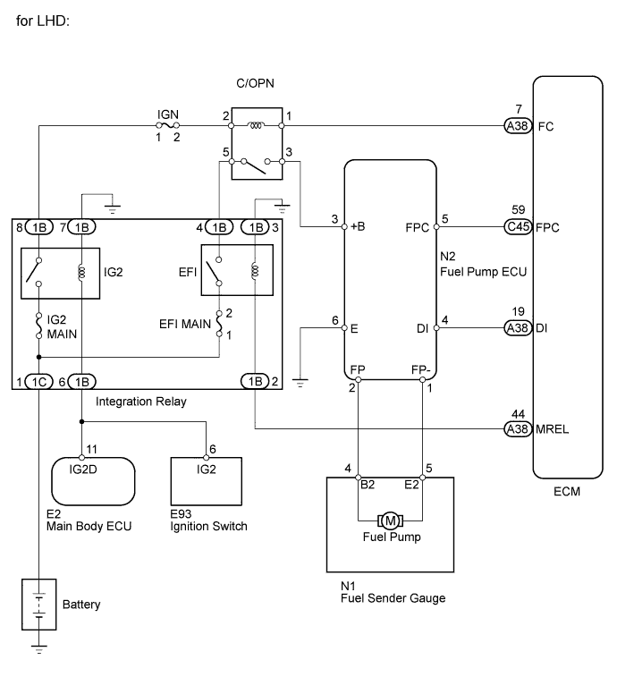
Wiring diagram

Inspection procedure
This troubleshooting procedure is based on the premise that the engine is started. If the engine is not started, proceed to the Problem Symptoms Table.
1.CHECK DTC OUTPUT
-
Connect the intelligent tester to the DLC3.
-
Turn the ignition switch to ON.
-
Enter the following menus: Body / (desired system) / DTC.
-
Read the DTC.
Result Result Proceed to DTC B1500 is not output A DTC B1500 is output B
|
|
||||
| A | |
2.PERFORM ACTIVE TEST USING INTELLIGENT TESTER
-
Connect the intelligent tester to the DLC3.
-
Turn the ignition switch to ON and turn the tester on.
-
Enter the following menus: Powertrain / Engine and ECT / Active Test / Control the fuel pump / Speed.
-
Check whether operating sounds can be heard while operating the relay using the tester.
OK:
Operating sounds can be heard from circuit opening relay.
|
|
||||
| OK | |
3.CHECK HARNESS AND CONNECTOR (FUEL PUMP ECU - ECM, BODY GROUND)

-
Disconnect the fuel pump ECU connector.
-
Disconnect the ECM connector.
-
Measure the resistance according to the value(s) in the table below.
Standard Resistance (Check for Open):
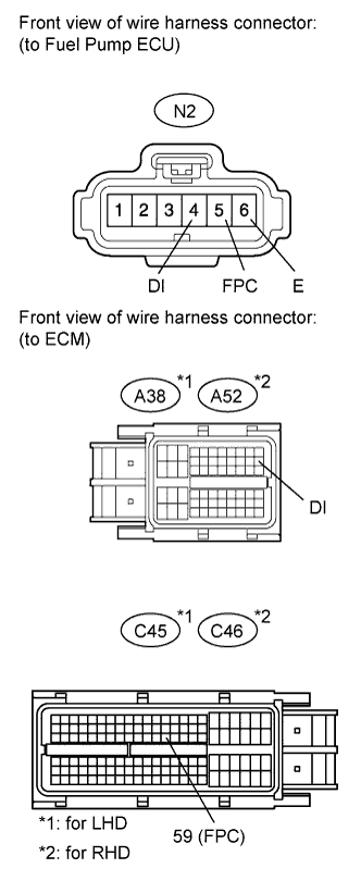
for LHD Tester Connection Condition Specified Condition N2-5 (FPC) - C45-59 (FPC) Always Below 1 ? N2-4 (DI) - A38-19 (DI) Always Below 1 ? N2-6 (E) - Body ground Always Below 1 ? for RHD Tester Connection Condition Specified Condition N2-5 (FPC) - C46-59 (FPC) Always Below 1 ? N2-4 (DI) - A52-19 (DI) Always Below 1 ? N2-6 (E) - Body ground Always Below 1 ? Standard Resistance (Check for Short):
for LHD Tester Connection Condition Specified Condition N2-1 (FP-) - Body ground Always 10 k? or higher N2-5 (FPC) or C45-59 (FPC) - Body ground Always 10 k? or higher N2-4 (DI) or A38-19 (DI) - Body ground Always 10 k? or higher for RHD Tester Connection Condition Specified Condition N2-1 (FP-) - Body ground Always 10 k? or higher N2-5 (FPC) or C46-59 (FPC) - Body ground Always 10 k? or higher N2-4 (DI) or A52-19 (DI) - Body ground Always 10 k? or higher
|
|
||||
| OK | |
4.REPLACE FUEL PUMP ECU
-
Replace the fuel pump ECU.
| NEXT | |
5.CHECK WHETHER DTC OUTPUT RECURS
-
Check that there are 17 liters or more of fuel remaining.
-
Connect the intelligent tester to the DLC3.
-
Turn the ignition switch to ON.
-
Turn the tester on.
-
Clear the DTCs.
-
Start the engine and idle it for 5 minutes.
-
Drive the vehicle in an urban area for approximately 10 minutes.
-
Enter the following menus: Powertrain / Engine and ECT / DTC.
-
Read the DTCs.
Result Result Proceed to No output A DTC P0230 is output B
|
|
||||
| A | |
|
6.INSPECT CIRCUIT OPENING RELAY (C/OPN)
-
Inspect the circuit opening relay (C/OPN).
|
|
||||
| OK | |
7.INSPECT CIRCUIT OPENING RELAY (C/OPN) (POWER SOURCE VOLTAGE)

-
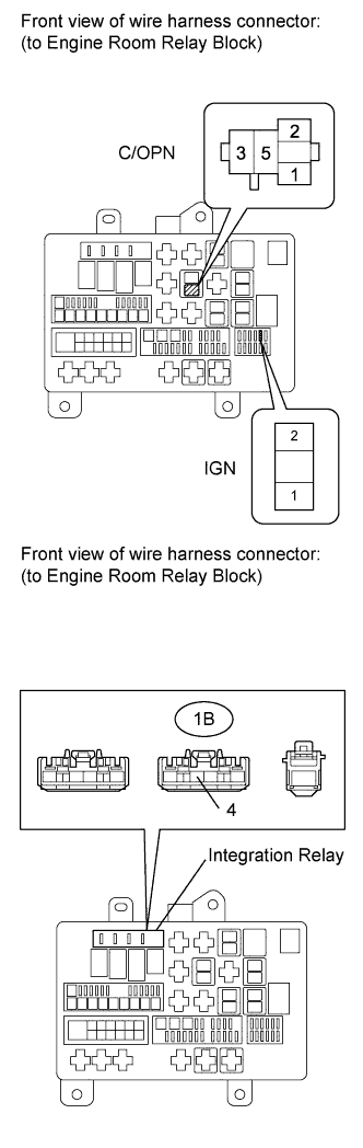
Remove the circuit opening relay (C/OPN) from the engine room relay block.
-
Measure the voltage according to the value(s) in the table below.
Standard Voltage:
Tester Connection Switch Condition Specified Condition C/OPN relay (2) - Body ground Ignition switch ON 11 to 14 V C/OPN relay (5) - Body ground Ignition switch ON 11 to 14 V
|
|
||||
| OK | |
8.CHECK HARNESS AND CONNECTOR (C/OPN RELAY - ECM, FUEL PUMP ECU)

-
Remove the circuit opening relay (C/OPN) from the engine room relay block.
-
Disconnect the fuel pump ECU connector.
-
Disconnect the ECM connector.
-
Measure the resistance according to the value(s) in the table below.
Standard Resistance (Check for Open):
for LHD Tester Connection Condition Specified Condition C/OPN relay (1) - A38-7 (FC) Always Below 1 ? C/OPN relay (3) - N2-3 (+B) Always Below 1 ? for RHD Tester Connection Condition Specified Condition C/OPN relay (1) - A52-7 (FC) Always Below 1 ? C/OPN relay (3) - N2-3 (+B) Always Below 1 ? Standard Resistance (Check for Short):
for LHD Tester Connection Condition Specified Condition C/OPN relay (1) or A38-7 (FC) - Body ground Always 10 k? or higher C/OPN relay (3) or N2-3 (+B) - Body ground Always 10 k? or higher for RHD Tester Connection Condition Specified Condition C/OPN relay (1) or A52-7 (FC) - Body ground Always 10 k? or higher C/OPN relay (3) or N2-3 (+B) - Body ground Always 10 k? or higher
|
|
||||
| OK | |
9.CHECK HARNESS AND CONNECTOR (FUEL PUMP - FUEL PUMP ECU)

-
Disconnect the fuel sender gauge connector.
-
Disconnect the fuel pump ECU connector.
-
Measure the resistance according to the value(s) in the table below.
Standard Resistance (Check for Open):
Tester Connection Condition Specified Condition N1-4 (B2) - N2-2 (FP) Always Below 1 ? N1-5 (E2) - N2-1 (FP-) Always Below 1 ? Standard Resistance (Check for Short):
Tester Connection Condition Specified Condition N1-4 (B2) or N2-2 (FP) - Body ground Always 10 k? or higher N1-5 (E2) or N2-1 (FP-) - Body ground Always 10 k? or higher
|
|
||||
| OK | |
10.INSPECT FUEL PUMP
-
Inspect the fuel pump (for Single Tank Type).
-
Inspect the fuel pump (for Double Tank Type).
Result Test Result Proceed to OK A NG (for Single Tank Type) B NG (for Double Tank Type) C
|
|
||||
|
|
||||
| A | |
11.CHECK HARNESS AND CONNECTOR (FUEL PUMP ECU - ECM, BODY GROUND)
-
Disconnect the fuel pump ECU connector.
-
Disconnect the ECM connector.
-
Measure the resistance according to the value(s) in the table below.
Standard Resistance (Check for Open):
for LHD Tester Connection Condition Specified Condition N2-5 (FPC) - C45-59 (FPC) Always Below 1 ? N2-4 (DI) - A38-19 (DI) Always Below 1 ? N2-6 (E) - Body ground Always Below 1 ? for RHD Tester Connection Condition Specified Condition N2-5 (FPC) - C46-59 (FPC) Always Below 1 ? N2-4 (DI) - A52-19 (DI) Always Below 1 ? N2-6 (E) - Body ground Always Below 1 ? Standard Resistance (Check for Short):
for LHD Tester Connection Condition Specified Condition N2-5 (FPC) or C45-59 (FPC) - Body ground Always 10 k? or higher N2-4 (DI) or A38-19 (DI) - Body ground Always 10 k? or higher for RHD Tester Connection Condition Specified Condition N2-5 (FPC) or C46-59 (FPC) - Body ground Always 10 k? or higher N2-4 (DI) or A52-19 (DI) - Body ground Always 10 k? or higher
|
|
||||
| OK | |
12.REPLACE FUEL PUMP ECU
-
Replace the fuel pump ECU.
| NEXT | |
13.CHECK WHETHER DTC OUTPUT RECURS
-
Conecte el probador inteligente al DLC3.
-
Gire el interruptor de encendido a ON.
-
Encienda el probador.
-
Borre los DTC.
-
Arranque el motor y dejelo al ralenti durante 5 minutos.
-
Conduzca el vehiculo en una zona urbana durante aproximadamente 10 minutos.
-
Ingrese a los siguientes menus: Powertrain / Engine y ECT / DTC.
-
Lea los DTC.
Resultado Resultado Proceder a Ninguna salida A Se emite el DTC P0230 B
|
|
||||
| A | |
|
14.INSPECCIONE EL MAZO DE CABLES Y EL CONECTOR (RELE DE APERTURA DEL CIRCUITO (C/OPN) - FUSIBLE DE ENCENDIDO, RELE DE INTEGRACION)
-
Retire el rele de apertura del circuito (C/OPN) del bloque de reles de la sala de maquinas.
-
Retire el fusible IGN del bloque de reles de la sala de maquinas.
-
Retire el rele de integracion del bloque de reles de la sala de maquinas.
-
Desconecte el conector del rele de integracion 1B.
-
Mida la resistencia de acuerdo con los valores de la siguiente tabla.
Resistencia estandar (compruebe si esta abierta):
Conexion del probador Condicion Condicion especificada Rele C/OPN (2) - Fusible IGN (2) Siempre por debajo de 1? Rele C/OPN (5) - 1B-4 Siempre por debajo de 1? Resistencia estandar (compruebe si hay cortocircuito):
Conexion del probador Condicion Condicion especificada Rele C/OPN (2) o fusible IGN (2) - Masa carroceria Siempre 10k?o mas Rele C/OPN (5) o 1B-4 - Masa carroceria Siempre 10k?o mas
|
|
||||
| OK | |
|