Двигатель. COROLLA, AURIS. ZZE150 ZRE151,152 NDE150
DESCRIPTION
WIRING DIAGRAM
INSPECTION PROCEDURE
CHECK ANY OTHER DTCS OUTPUT (IN ADDITION TO DTC P1229 AND/OR P1272)
CONFIRM IF VEHICLE HAS RUN OUT OF FUEL IN PAST
PERFORM ACTIVE TEST USING INTELLIGENT TESTER (FUEL LEAK TEST)
CHECK FUEL LINE (FUEL BLOCKAGES)
INSPECT COMMON RAIL ASSEMBLY (PRESSURE CONTROL VALVE ASSEMBLY)
CHECK COMMON RAIL ASSEMBLY (PRESSURE CONTROL VALVE POWER SOURCE)
CHECK HARNESS AND CONNECTOR (PRESSURE CONTROL VALVE - ECM)
INSPECT SUPPLY PUMP ASSEMBLY (SUCTION CONTROL VALVE)
CHECK SUPPLY PUMP ASSEMBLY (SUCTION CONTROL VALVE VOLTAGE)
CHECK HARNESS AND CONNECTOR (SUPPLY PUMP ASSEMBLY - ECM)
REPLACE COMMON RAIL ASSEMBLY (PRESSURE CONTROL VALVE)
CHECK WHETHER DTC OUTPUT RECURS (DTC P1229 AND/OR P1272)
REPLACE SUPPLY PUMP ASSEMBLY (SUCTION CONTROL VALVE)
CHECK WHETHER DTC OUTPUT RECURS (DTC P1229 AND/OR P1272)
REPLACE INJECTOR ASSEMBLY
CHECK WHETHER DTC OUTPUT RECURS (P1229 AND/OR P1272)
INSPECT FUSE (EFI NO. 2 FUSE)
INSPECT FUSE (EFI NO. 2 FUSE)
DTC P1229 Fuel Pump System |
DTC P1272 Fuel Pressure Regulator System Malfunction |
DESCRIPTION
Refer to DTC P0089 (See page Нажмите здесь) and DTC P0252 (See page Нажмите здесь).DTC No.
| DTC Detection Condition
| Trouble Area
|
P1229
| When common rail internal pressure is regulated using suction control valve, it does not reach target pressure level or it exceeds target level by too much
(The MIL is illuminated and a DTC is immediately set when a malfunction is detected)
| - Supply pump (suction control valve)
- Short in supply pump (suction control valve) circuit
- Open in pressure control valve circuit
- Pressure control valve
- Fuel filter element is clogged
- Fuel leak
- Injector
- Lack of fuel
- ECM
|
P1272
| When common rail internal pressure is regulated using pressure control valve, it does not reach target pressure level or it exceeds target level by too much
(The MIL is illuminated and a DTC is immediately set when a malfunction is detected)
|
- УКАЗАНИЕ:
- DTC P1229 is set when the vehicle is driven (including acceleration and deceleration) at a vehicle speed of over 50 km/h (31 mph) for more than 5 minutes, while the fuel temperature is more than 10°C (50°F) and the engine coolant temperature is higher than the fuel temperature.
- DTC P1272 is set when the vehicle is driven (including acceleration and deceleration) at a vehicle speed of over 50 km/h (31 mph) for more than 5 minutes, while the fuel temperature is more than 10°C (50°F) and the engine coolant temperature is higher than the fuel temperature.
- DTCs P1229 and/or P1272 may be set if the vehicle is driven with insufficient fuel.
- With cold engine, the internal pressure of the common rail is regulated by the pressure control valve.
With warm engine, it is regulated by the suction control valve.
- When DTC P1229 and/or P1272 is set, check the internal fuel pressure of the common rail by selecting the following menu items on the intelligent tester: Powertrain / Engine and ECT / Data List / Common Rail Pressure.
- Reference:
Engine Speed
| Fuel Pressure
|
Idling
| Approximately 25 to 36 MPa
|
2000 rpm (No engine load)
| Approximately 27 to 46 MPa
|
3000 rpm (No engine load)
| Approximately 34 to 69 MPa
|
WIRING DIAGRAM
Refer to DTC P0089 (See page Нажмите здесь).Refer to DTC P0252 (See page Нажмите здесь).
INSPECTION PROCEDURE
- УКАЗАНИЕ:
- Read freeze frame data using an intelligent tester. The ECM records vehicle and driving condition information as freeze frame data the moment a DTC is stored. When troubleshooting, freeze frame data can be helpful in determining whether the vehicle was running or stopped, whether the engine was warmed up or not, whether the air fuel ratio was lean or rich, as well as other data recorded at the time of a malfunction.
| 1.CHECK ANY OTHER DTCS OUTPUT (IN ADDITION TO DTC P1229 AND/OR P1272) |
Connect the intelligent tester to the DLC3.
Turn the ignition switch to the ON position.
Turn the tester on.
Enter the following menu items: Powertrain / Engine and ECT / DTC.
Read the DTCs.
- Result:
Result
| Proceed to
|
DTC P1229 and/or P1272 are output
| A
|
DTC P1229 and/or P1272 and other DTCs are output
| B
|
| 2.CONFIRM IF VEHICLE HAS RUN OUT OF FUEL IN PAST |
Ask the customer whether the fuel has run out recently.
Ask the customer whether repetitive quick turns were made while the fuel was low.
- Result:
Result
| Proceed to
|
- Fuel not run out recently
- Quick turns not repeated when fuel low
| A
|
- Fuel run out recently
- Quick turns repeated when fuel low
| B
|
| | DTC CAUSED BY RUNNING OUT OF FUEL |
|
|
| 3.PERFORM ACTIVE TEST USING INTELLIGENT TESTER (FUEL LEAK TEST) |
Connect the intelligent tester to the DLC3.
Start the engine.
Turn the tester on.
Enter the following menu items: Powertrain / Engine and ECT / Active Test / Fuel leak test.
Visually check the supply pump, injector and fuel line located between the supply pump and common rail for fuel leaks. Also, perform the same check on the fuel line between the common rail and the injector (See page Нажмите здесь).
- УКАЗАНИЕ:
- There may be fuel leaks inside the components, such as the supply pump.
- OK:
- No leakage.
| 4.CHECK FUEL LINE (FUEL BLOCKAGES) |
Check for fuel line for blockages.
- OK:
- No blockage.
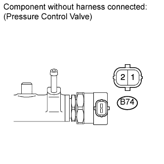
| 5.INSPECT COMMON RAIL ASSEMBLY (PRESSURE CONTROL VALVE ASSEMBLY) |
Disconnect the pressure control valve connector.
Measure the resistance according to the value(s) in the table below.
- Standard resistance:
Tester Connection
| Condition
| Specified Condition
|
B74-1 - B74-2
| 20°C (68°F)
| 3.42 to 3.78 Ω
|
Reconnect the pressure control valve connector.
| | REPLACE COMMON RAIL ASSEMBLY (PRESSURE CONTROL VALVE) (Нажмите здесь) |
|
|
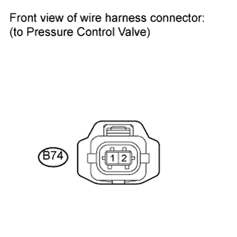
| 6.CHECK COMMON RAIL ASSEMBLY (PRESSURE CONTROL VALVE POWER SOURCE) |
Disconnect the pressure control valve connector.
Turn the ignition switch to the ON position.
Measure the voltage according to the value(s) in the table below.
- Standard voltage:
Tester Connection
| Switch Condition
| Specified Condition
|
B74-1 - Body ground
| Ignition switch ON
| 9 to 14 V
|
Turn the ignition switch off.
Reconnect the pressure control valve connector.
| 7.CHECK HARNESS AND CONNECTOR (PRESSURE CONTROL VALVE - ECM) |
Disconnect the ECM connector.
Disconnect the pressure control valve connector.
Measure the resistance according to the value(s) in the table below.
- Standard resistance (check for open):
Tester Connection
| Condition
| Specified Condition
|
B77-4 (PRV) - B74-2
| Always
| Below 1 Ω
|
- Standard resistance (check for short):
Tester Connection
| Condition
| Specified Condition
|
B77-4 (PRV) or B74-2 - Body ground
| Always
| 10 kΩ or higher
|
Reconnect the pressure control valve connector.
Reconnect the ECM connector.
| | REPAIR OR REPLACE HARNESS OR CONNECTOR (PRESSURE CONTROL VALVE - ECM) |
|
|
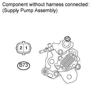
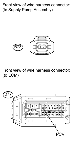
| 8.INSPECT SUPPLY PUMP ASSEMBLY (SUCTION CONTROL VALVE) |
Disconnect the supply pump assembly connector.
Measure the resistance according to the value(s) in the table below.
- Standard resistance:
Tester Connection
| Condition
| Specified Condition
|
B73-1 - B73-2
| 20°C (68°F)
| 2.6 to 3.15 Ω
|
Reconnect the supply pump assembly connector.
| | REPLACE SUPPLY PUMP ASSEMBLY (SUCTION CONTROL VALVE) (Нажмите здесь) |
|
|
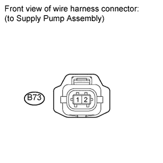
| 9.CHECK SUPPLY PUMP ASSEMBLY (SUCTION CONTROL VALVE VOLTAGE) |
Disconnect the supply pump assembly connector.
Turn the ignition switch to the ON position.
Measure the voltage according to the value(s) in the table below.
- Standard voltage:
Tester Connection
| Switch Condition
| Specified Condition
|
B73-1 - Body ground
| Ignition switch ON
| 9 to 14 V
|
Reconnect the supply pump assembly connector.
| 10.CHECK HARNESS AND CONNECTOR (SUPPLY PUMP ASSEMBLY - ECM) |
Disconnect the supply pump assembly connector.
Disconnect the ECM connector.
Measure the resistance according to the value(s) in the table below.
- Standard resistance (check for open):
Tester Connection
| Condition
| Specified Condition
|
B73-2 - B77-12 (PCV)
| Always
| Below 1 Ω
|
- Standard resistance (check for short):
Tester Connection
| Condition
| Specified Condition
|
B73-2 or B77-12 (PCV) - Body ground
| Always
| 10 kΩ or higher
|
Reconnect the ECM connector.
Reconnect the supply pump assembly connector.
| | REPAIR OR REPLACE HARNESS OR CONNECTOR (SUPPLY PUMP ASSEMBLY - ECM) |
|
|
| 11.REPLACE COMMON RAIL ASSEMBLY (PRESSURE CONTROL VALVE) |
Replace the common rail assembly (See page Нажмите здесь).
| 12.CHECK WHETHER DTC OUTPUT RECURS (DTC P1229 AND/OR P1272) |
Connect the intelligent tester to the DLC3.
Turn the ignition switch to the ON position.
Turn the tester on.
Clear the DTCs (See page Нажмите здесь).
Drive the vehicle at 50 km/h (31 mph) for more than 5 minutes while the fuel temperature is more than 10°C (50°F).
Drive the vehicle at 50 km/h (31 mph) for more than 5 minutes while the fuel temperature is less than 10°C (50°F).
Enter the following menu items: Powertrain / Engine and ECT / DTC.
Read the DTCs.
- Result:
Result
| Proceed to
|
DTC P1229 and/or P1272 are output
| A
|
DTC is not output
| B
|
| 13.REPLACE SUPPLY PUMP ASSEMBLY (SUCTION CONTROL VALVE) |
Replace the fuel supply pump assembly (See page Нажмите здесь).
| 14.CHECK WHETHER DTC OUTPUT RECURS (DTC P1229 AND/OR P1272) |
Connect the intelligent tester to the DLC3.
Turn the ignition switch to the ON position.
Turn the tester on.
Clear the DTCs (See page Нажмите здесь).
Drive the vehicle at 50 km/h (31 mph) for more than 5 minutes while the fuel temperature is more than 10°C (50°F).
Drive the vehicle at 50 km/h (31 mph) for more than 5 minutes while the fuel temperature is less than 10°C (50°F).
Enter the following menu items: Powertrain / Engine and ECT / DTC.
Read the DTCs.
- Result:
Result
| Proceed to
|
DTC P1229 and/or P1272 are output
| A
|
DTC is not output
| B
|
| 15.REPLACE INJECTOR ASSEMBLY |
Replace the injector assembly (See page Нажмите здесь).
| 16.CHECK WHETHER DTC OUTPUT RECURS (P1229 AND/OR P1272) |
Connect the intelligent tester to the DLC3.
Turn the ignition switch to the ON position.
Turn the tester on.
Enter the following menu items: Powertrain / Engine and ECT / DTC.
Read the DTCs.
- Result:
Result
| Proceed to
|
DTC P1229 and/or P1272 are output
| A
|
DTC is not output
| B
|
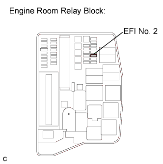
| 17.INSPECT FUSE (EFI NO. 2 FUSE) |
Remove the EFI No. 2 fuse from the engine room relay block.
Measure the resistance according to the value(s) in the table below.
- Standard resistance:
Tester Connection
| Condition
| Specified Condition
|
EFI No. 2 fuse
| Always
| Below 1 Ω
|
Reinstall the EFI No. 2 fuse.
| | REPLACE FUSE (EFI NO. 2 FUSE) |
|
|
| OK |
|
|
|
| REPAIR OR REPLACE HARNESS OR CONNECTOR (PRESSURE CONTROL VALVE - INTEGRATION RELAY (EFI MAIN RELAY)) |
|
| 18.INSPECT FUSE (EFI NO. 2 FUSE) |
Remove the EFI No. 2 fuse from the engine room relay block.
Measure the resistance according to the value(s) in the table below.
- Standard resistance:
Tester Connection
| Condition
| Specified Condition
|
EFI No. 2 fuse
| Always
| Below 1 Ω
|
Reinstall the EFI No. 2 fuse.
| | REPLACE FUSE (EFI NO. 2 FUSE) |
|
|
| OK |
|
|
|
| REPAIR OR REPLACE HARNESS OR CONNECTOR (SUCTION CONTROL VALVE - INTEGRATION RELAY (EFI MAIN RELAY)) |
|