Manual Transmission Assembly Removal
DISCONNECT CABLE FROM NEGATIVE BATTERY TERMINAL
REMOVE SHIFT LEVER KNOB SUB-ASSEMBLY
REMOVE REAR CONSOLE PANEL SUB-ASSEMBLY
REMOVE FRONT CONSOLE PANEL SUB-ASSEMBLY
REMOVE FRONT ASH RECEPTACLE SUB-ASSEMBLY
REMOVE CONSOLE BOX REGISTER ASSEMBLY
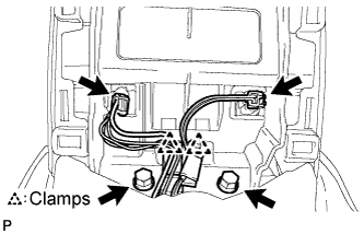
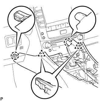
REMOVE CONSOLE BOX
REMOVE NO. 2 CONSOLE BOX DUCT
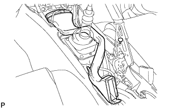
REMOVE NO. 1 SHIFT AND SELECT LEVER BOOT
REMOVE SHIFT LEVER CAP
REMOVE ENGINE UNDER COVER
REMOVE NO. 2 ENGINE UNDER COVER
DRAIN MANUAL TRANSMISSION OIL
REMOVE NO. 1 REAR FLOOR PANEL BRACE
REMOVE FRONT CENTER FLOOR BRACE
DISCONNECT HEATED OXYGEN SENSOR
REMOVE FRONT EXHAUST PIPE ASSEMBLY
REMOVE FRONT FLOOR NO. 1 HEAT INSULATOR
REMOVE OUTSIDE AIR GUIDE PLATE RH
REMOVE PROPELLER SHAFT WITH CENTER BEARING ASSEMBLY
REMOVE ENGINE UNDER COVER AIR GUIDE BRACKET
REMOVE STARTER ASSEMBLY
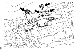
SEPARATE CLUTCH ACCUMULATOR ASSEMBLY
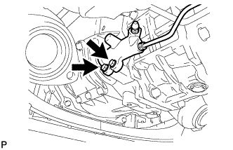
SEPARATE CLUTCH RELEASE CYLINDER ASSEMBLY
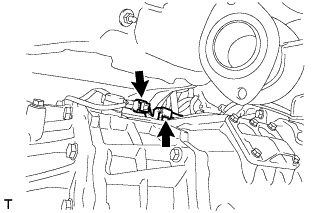
DISCONNECT GROUND CABLE
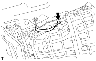
SEPARATE WIRE HARNESS
REMOVE NO. 1 CLUTCH HOUSING COVER
REMOVE NO. 2 CLUTCH HOUSING COVER
SEPARATE CLUTCH COVER ASSEMBLY
SEPARATE FLOOR SHIFT CONTROL SHIFT LEVER RETAINER SUB-ASSEMBLY
REMOVE FLOOR SHIFT LEVER ASSEMBLY
SUPPORT MANUAL TRANSMISSION ASSEMBLY
REMOVE ENGINE REAR MOUNTING MEMBER
REMOVE MANUAL TRANSMISSION ASSEMBLY
REMOVE CLUTCH RELEASE FORK SUB-ASSEMBLY
REMOVE CLUTCH DISC ASSEMBLY
REMOVE CLUTCH COVER ASSEMBLY
REMOVE REAR NO. 1 ENGINE MOUNTING INSULATOR
REMOVE TRANSMISSION UPPER COVER SUB-ASSEMBLY
Manual Transmission Assembly -- Removal |
| 1. DISCONNECT CABLE FROM NEGATIVE BATTERY TERMINAL |
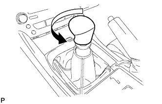
| 2. REMOVE SHIFT LEVER KNOB SUB-ASSEMBLY |
Turn the shift lever knob counterclockwise and remove the shift lever knob sub-assembly.
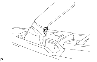
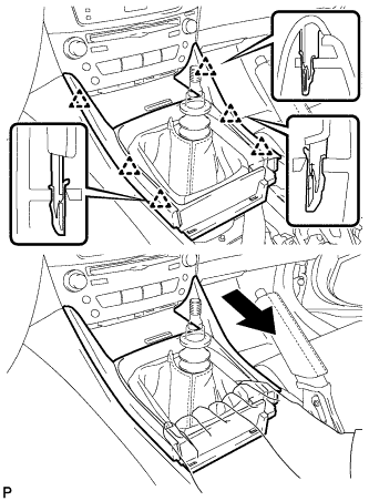
| 3. REMOVE REAR CONSOLE PANEL SUB-ASSEMBLY |
Open the snap.
Disengage the 7 claws and 2 clips, and then remove the rear console panel sub-assembly.
| 4. REMOVE FRONT CONSOLE PANEL SUB-ASSEMBLY |
Open the snap.
Pull the front console panel sub-assembly in the direction indicated by the arrow to disengage the 6 clips and remove it.
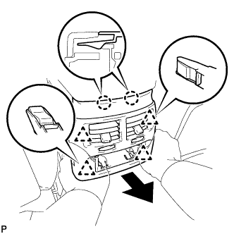
| 5. REMOVE FRONT ASH RECEPTACLE SUB-ASSEMBLY |
Remove the 2 screws <F>.
Pull the front ash receptacle sub-assembly in the direction indicated by the arrow to disconnect the connectors and remove it.
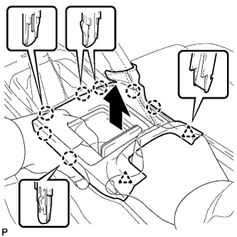
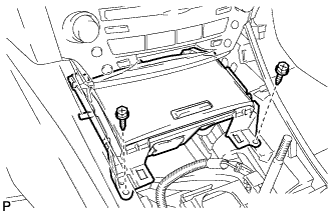
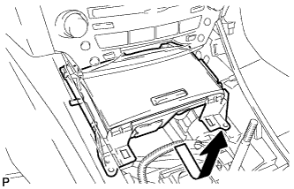
| 6. REMOVE CONSOLE BOX REGISTER ASSEMBLY |
Remove the rear ash receptacle assembly.
Disengage the 2 claws and 4 clips, and then remove the console box register assembly.
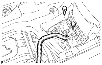
Remove the 2 bolts <C>.
Disconnect the 2 connectors.
Disengage the 2 clamps.
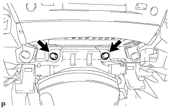
Remove the 2 bolts <C>.
Disconnect the connector.
Remove the 2 bolts <C>.
Disengage the 2 claws and 2 clips, and then remove the console box.
| 8. REMOVE NO. 2 CONSOLE BOX DUCT |
Remove the clip and No. 2 console box duct.
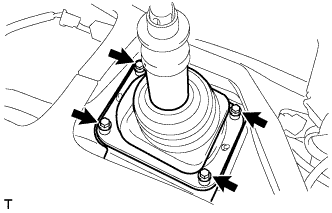
| 9. REMOVE NO. 1 SHIFT AND SELECT LEVER BOOT |
Remove the 4 bolts and No. 1 shift and select lever boot.
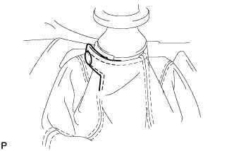
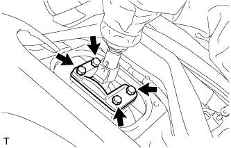
| 10. REMOVE SHIFT LEVER CAP |
Turn over the shift lever dust cover.
Remove the 4 bolts and shift lever cap.
| 11. REMOVE ENGINE UNDER COVER |
| 12. REMOVE NO. 2 ENGINE UNDER COVER |
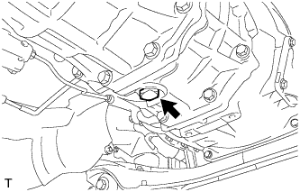
| 13. DRAIN MANUAL TRANSMISSION OIL |
Remove the drain plug and gasket, and drain the transmission oil.
Install a new gasket and the drain plug.
- Torque:
- 37 N*m{377 kgf*cm, 27 ft.*lbf}
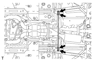
| 14. REMOVE NO. 1 REAR FLOOR PANEL BRACE |
Remove the 4 bolts and rear No. 1 floor panel brace.
| 15. REMOVE FRONT CENTER FLOOR BRACE |
Remove the 4 bolts and front center floor brace .
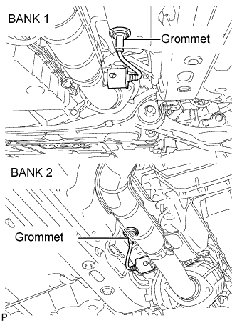
| 16. DISCONNECT HEATED OXYGEN SENSOR |
Remove the grommets of the heated oxygen sensors (BANK 1, BANK 2).
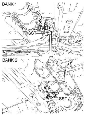
Using the SST, remove a oxygen sensors (BANK 1, BANK 2).
- SST
- 09224-00010
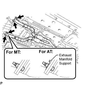
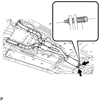
| 17. REMOVE FRONT EXHAUST PIPE ASSEMBLY |
Remove the 4 bolts and 4 nuts.
Remove the 2 bolts and 2 compression springs from the tail exhaust pipe assembly.
Remove the front exhaust pipe assembly and 3 gaskets.
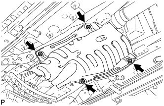
| 18. REMOVE FRONT FLOOR NO. 1 HEAT INSULATOR |
Remove the 4 nuts and front No. 1 floor heat insulator.
| 19. REMOVE OUTSIDE AIR GUIDE PLATE RH |
Remove the 4 nuts and outside air guide plate RH.
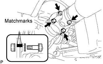
| 20. REMOVE PROPELLER SHAFT WITH CENTER BEARING ASSEMBLY |
Put matchmarks on both flanges.
Remove the 4 nuts, bolts and washers.
- HINT:
- If the flange connection is hard to separate, temporarily tighten one nut only and evenly tap the flange with a brass bar and hammer to separate the propeller shaft assembly from the differential companion flange.
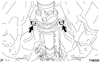
Remove the 2 bolts and 2 center support bearing washers. (for automatic transmission)
Remove the 2 bolts, 2 center support bearing washers and 2 center support bearing dampers. (for manual transmission)
Separate the center support bearing.
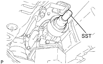
Insert SST in the transmission to prevent oil leakage.
- SST
- 09325-40010
- NOTICE:
- Be careful not to damage the oil seal.
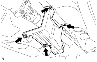
| 21. REMOVE ENGINE UNDER COVER AIR GUIDE BRACKET |
Remove the 2 bolts and engine under cover air guide bracket.
| 22. REMOVE STARTER ASSEMBLY |
(Click here)
| 23. SEPARATE CLUTCH ACCUMULATOR ASSEMBLY |
Remove the 2 bolts and 2 nuts, and separate the clutch accumulator assembly.
| 24. SEPARATE CLUTCH RELEASE CYLINDER ASSEMBLY |
Remove the 2 bolts and separate the clutch release cylinder assembly.
| 25. DISCONNECT GROUND CABLE |
Remove the bolt and disconnect the ground cable.
| 26. SEPARATE WIRE HARNESS |
Disconnect the back-up lamp switch connector and separate the wire harness.
| 27. REMOVE NO. 1 CLUTCH HOUSING COVER |
Remove the 4 bolts and No. 1 clutch housing cover.
| 28. REMOVE NO. 2 CLUTCH HOUSING COVER |
Remove the 4 bolts and No. 2 clutch housing cover.
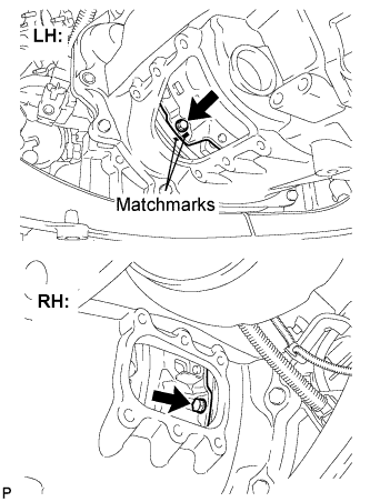
| 29. SEPARATE CLUTCH COVER ASSEMBLY |
Put matchmarks on the clutch cover assembly and the flywheel sub-assembly.
Loosen each set bolt one turn at a time until spring tension is released.
Remove the 6 bolts and separate the clutch cover assembly.
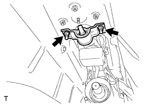
| 30. SEPARATE FLOOR SHIFT CONTROL SHIFT LEVER RETAINER SUB-ASSEMBLY |
Remove the 2 nuts and separate the floor shift control shift lever retainer sub-assembly.
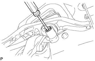
| 31. REMOVE FLOOR SHIFT LEVER ASSEMBLY |
Turn over the shift and select lever boot.
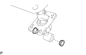
Using a screwdriver, remove the E-ring and floor shift lever assembly.
Remove the washer from the floor shift lever assembly.
Remove the 2 bushings from the floor shift lever assembly.
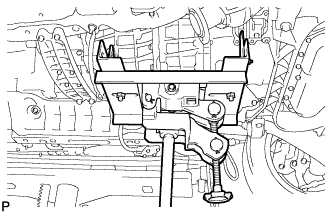
| 32. SUPPORT MANUAL TRANSMISSION ASSEMBLY |
Support the manual transmission with a transmission jack.
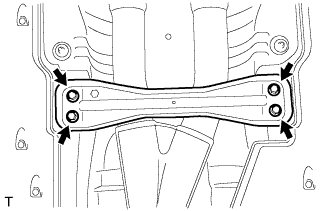
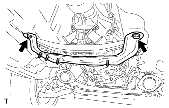
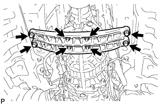
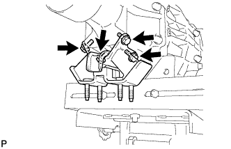
| 33. REMOVE ENGINE REAR MOUNTING MEMBER |
Remove the 4 bolts, 4 nuts and engine rear mounting member.
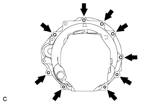
| 34. REMOVE MANUAL TRANSMISSION ASSEMBLY |
Remove the 9 bolts and manual transmission assembly.
| 35. REMOVE CLUTCH RELEASE FORK SUB-ASSEMBLY |
Remove the clutch release fork sub-assembly from the transmission unit.
| 36. REMOVE CLUTCH DISC ASSEMBLY |
- NOTICE:
- Keep the lining part of the clutch disc assembly, the pressure plate and surface of the flywheel sub-assembly away from oil and foreign matter.
| 37. REMOVE CLUTCH COVER ASSEMBLY |
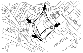
| 38. REMOVE REAR NO. 1 ENGINE MOUNTING INSULATOR |
Remove the 4 bolts and rear No. 1 engine mounting insulator.
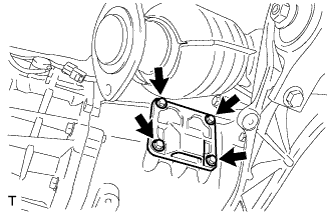
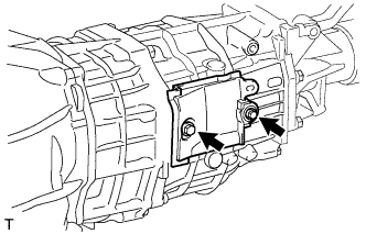
| 39. REMOVE TRANSMISSION UPPER COVER SUB-ASSEMBLY |
Remove the 2 bolts and transmission upper cover sub-assembly.