REMOVE FRONT FENDER SPLASH SHIELD SUB-ASSEMBLY LH
REMOVE FRONT FENDER SPLASH SHIELD SUB-ASSEMBLY RH
REMOVE NO. 1 ENGINE UNDER COVER SUB-ASSEMBLY
REMOVE NO. 2 ENGINE UNDER COVER
REMOVE FRONT FENDER APRON SEAL FRONT RH
REMOVE FRONT FENDER APRON SEAL REAR RH
REMOVE FRONT FENDER APRON SEAL LH
REMOVE FRONT FENDER APRON SEAL REAR LH
REMOVE ENGINE OIL LEVEL DIPSTICK GUIDE
REMOVE TAILPIPE ASSEMBLY
REMOVE CENTER EXHAUST PIPE ASSEMBLY
REMOVE FRONT NO. 2 EXHAUST PIPE ASSEMBLY
REMOVE FRONT EXHAUST PIPE ASSEMBLY
REMOVE PROPELLER SHAFT HEAT INSULATOR
REMOVE NO. 2 MANIFOLD STAY
REMOVE NO. 2 EXHAUST MANIFOLD HEAT INSULATOR
REMOVE EXHAUST MANIFOLD SUB-ASSEMBLY LH
REMOVE NO. 1 MANIFOLD STAY
REMOVE NO. 1 EXHAUST MANIFOLD HEAT INSULATOR
REMOVE EXHAUST MANIFOLD SUB-ASSEMBLY RH
REMOVE AIR FUEL RATIO SENSOR (for Bank 1 Sensor 1)
REMOVE AIR FUEL RATIO SENSOR (for Bank 2 Sensor 1)
Exhaust Manifold -- Removal |
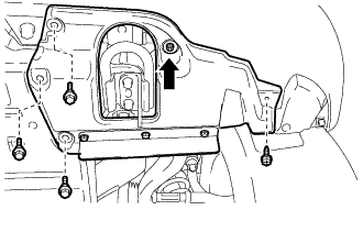
| 1. REMOVE FRONT FENDER SPLASH SHIELD SUB-ASSEMBLY LH |
Remove the 3 bolts and screw.
Turn the clip indicated by the arrow in the illustration to remove the front fender splash shield sub-assembly LH.
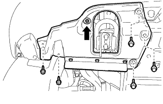
| 2. REMOVE FRONT FENDER SPLASH SHIELD SUB-ASSEMBLY RH |
Remove the 3 bolts and 2 screws.
Turn the clip indicated by the arrow in the illustration to remove the front fender splash shield sub-assembly RH.
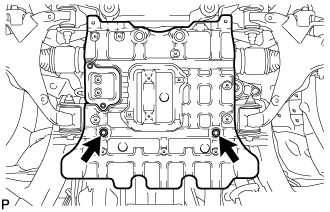
| 3. REMOVE NO. 1 ENGINE UNDER COVER SUB-ASSEMBLY |
Remove the 10 bolts and No. 1 engine under cover.
| 4. REMOVE NO. 2 ENGINE UNDER COVER |
Remove the 2 bolts and No. 2 engine under cover.
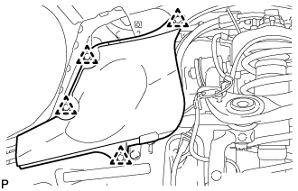
| 5. REMOVE FRONT FENDER APRON SEAL FRONT RH |
Using a clip remover, remove the 3 clips and fender apron seal.
| 6. REMOVE FRONT FENDER APRON SEAL REAR RH |
Using a clip remover, remove the 4 clips and fender apron seal.
| 7. REMOVE FRONT FENDER APRON SEAL LH |
Using a clip remover, remove the 3 clips and fender apron seal.
| 8. REMOVE FRONT FENDER APRON SEAL REAR LH |
Using a clip remover, remove the 4 clips and fender apron seal.
| 9. REMOVE ENGINE OIL LEVEL DIPSTICK GUIDE |
Disconnect the wire harness clamp.
Remove the dipstick.
Remove the bolt and dipstick guide.
Remove the O-ring from the dipstick guide.
| 10. REMOVE TAILPIPE ASSEMBLY |
Remove the bolt, clamp and gasket.
Remove the tailpipe from the 2 exhaust pipe supports.
Remove the bolt and clamp, and then disconnect the tailpipe from the center exhaust pipe.
| 11. REMOVE CENTER EXHAUST PIPE ASSEMBLY |
Remove the 4 bolts.
Remove the center exhaust pipe from the 3 exhaust pipe supports.
Remove the 2 gaskets from the front exhaust pipe and front No. 2 exhaust pipe.
| 12. REMOVE FRONT NO. 2 EXHAUST PIPE ASSEMBLY |
Disconnect the heated oxygen sensor connector.
Remove the bolt and disconnect the wire harness clamp bracket of the oxygen sensor from the transmission.
Remove the 2 nuts, front No. 2 exhaust pipe and gasket from the exhaust manifold LH.
| 13. REMOVE FRONT EXHAUST PIPE ASSEMBLY |
Disconnect the heated oxygen sensor connector.
Remove the bolt and disconnect the wire harness clamp bracket of the oxygen sensor from the transmission.
Remove the 2 nuts, front exhaust pipe and gasket from the exhaust manifold RH.
| 14. REMOVE PROPELLER SHAFT HEAT INSULATOR |
Remove the 2 bolts and heat insulator.
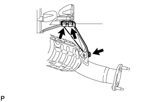
| 15. REMOVE NO. 2 MANIFOLD STAY |
Remove the 3 bolts and No. 2 manifold stay.
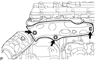
| 16. REMOVE NO. 2 EXHAUST MANIFOLD HEAT INSULATOR |
Remove the 3 bolts and heat insulator.
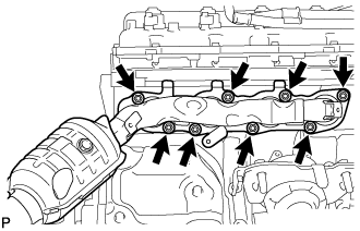
| 17. REMOVE EXHAUST MANIFOLD SUB-ASSEMBLY LH |
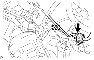
Disconnect the connector and detach the wire harness clamp.
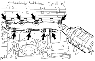
Remove the 8 nuts, exhaust manifold sub-assembly LH and gasket.
| 18. REMOVE NO. 1 MANIFOLD STAY |
Remove the 3 bolts and No. 1 manifold stay.
| 19. REMOVE NO. 1 EXHAUST MANIFOLD HEAT INSULATOR |
Remove the 3 bolts and heat insulator.
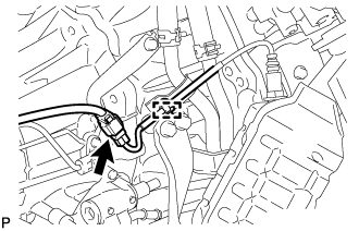
| 20. REMOVE EXHAUST MANIFOLD SUB-ASSEMBLY RH |
Disconnect the connector and detach the wire harness clamp.
Remove the 8 nuts, exhaust manifold sub-assembly RH and gasket.
| 21. REMOVE AIR FUEL RATIO SENSOR (for Bank 1 Sensor 1) |
Using SST, remove the sensor.
- SST
- 09224-00010
| 22. REMOVE AIR FUEL RATIO SENSOR (for Bank 2 Sensor 1) |
Using SST, remove the sensor.
- SST
- 09224-00010