DISCHARGE FUEL SYSTEM PRESSURE
PRECAUTION
DISCONNECT CABLE FROM NEGATIVE BATTERY TERMINAL
REMOVE V-BANK COVER SUB-ASSEMBLY
REMOVE AIR CLEANER HOSE ASSEMBLY
REMOVE NO. 1 ENGINE COVER SUB-ASSEMBLY
REMOVE NO. 3 ENGINE COVER
DISCONNECT NO. 2 FUEL TUBE
DISCONNECT NO. 1 FUEL TUBE
DISCONNECT NO. 1 FUEL HOSE
REMOVE FUEL DELIVERY PIPE SUB-ASSEMBLY RH
REMOVE FUEL DELIVERY PIPE SUB-ASSEMBLY LH
REMOVE FUEL INJECTOR ASSEMBLY
| 1. DISCHARGE FUEL SYSTEM PRESSURE |
(Click here)
- NOTICE:
- After turning the engine switch off, waiting time may be required before disconnecting the cable from the battery terminal. Therefore, make sure to read the disconnecting the cable from the battery terminal notice before proceeding with work (Click here).
| 3. DISCONNECT CABLE FROM NEGATIVE BATTERY TERMINAL |
- NOTICE:
- When disconnecting the cable, some systems need to be initialized after the cable is reconnected (Click here).
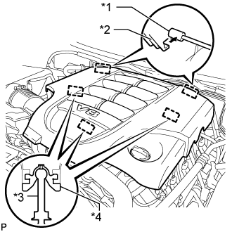
| 4. REMOVE V-BANK COVER SUB-ASSEMBLY |
Attach the 2 V-bank cover hooks to the bracket. Then align the 3 V-bank cover grommets with the 3 pins, and press down on the V-bank cover to attach the pins.
Text in Illustration*1
| Bracket
|
*2
| Hook
|
*3
| Pin
|
*4
| Grommet
|
| 5. REMOVE AIR CLEANER HOSE ASSEMBLY |
Disconnect the vacuum hose and No. 2 ventilation hose.
Loosen the 2 hose clamps.
Remove the air cleaner hose.
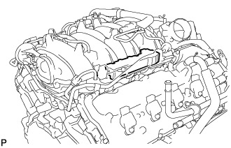
| 6. REMOVE NO. 1 ENGINE COVER SUB-ASSEMBLY |
Remove the No. 1 engine cover sub-assembly.
| 7. REMOVE NO. 3 ENGINE COVER |
Remove the No. 3 engine cover.
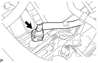
| 8. DISCONNECT NO. 2 FUEL TUBE |
Disconnect the No. 2 fuel tube from the fuel pressure regulator (Click here).
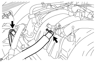
| 9. DISCONNECT NO. 1 FUEL TUBE |
Disconnect the No. 1 fuel tube from the fuel delivery pipe sub-assembly RH (for metallic type) (Click here).
- SST
- 09268-21011
Text in Illustration*A
| RH Side
|
LH Side:
Disconnect the No. 1 fuel tube from the fuel delivery pipe sub-assembly LH (Click here).
Text in Illustration*A
| LH Side
|
| 10. DISCONNECT NO. 1 FUEL HOSE |
Disconnect the No. 1 fuel hose from the fuel delivery pipe sub-assembly LH (Click here).
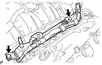
| 11. REMOVE FUEL DELIVERY PIPE SUB-ASSEMBLY RH |
Disconnect the ventilation hose and No. 6 wire harness connector.
Remove the 2 bolts and fuel delivery pipe sub-assembly RH.
- NOTICE:
- When removing the delivery pipe, hold the pipe by both ends and pull it straight upward.
Remove the 2 delivery pipe spacers and 4 insulators from the cylinder head RH.
| 12. REMOVE FUEL DELIVERY PIPE SUB-ASSEMBLY LH |
Disconnect the No. 7 wire harness connector.
Remove the 2 bolts and fuel delivery pipe sub-assembly LH.
- NOTICE:
- When removing the delivery pipe, hold the pipe by both ends and pull it straight upward.
Remove the 2 delivery pipe spacers and 4 insulators from the cylinder head LH.
| 13. REMOVE FUEL INJECTOR ASSEMBLY |
Remove the fuel injector assembly from the fuel delivery pipe, and then disconnect the injector connector.
- NOTICE:
- For reinstallation, attach a tag or label to the injector shaft.
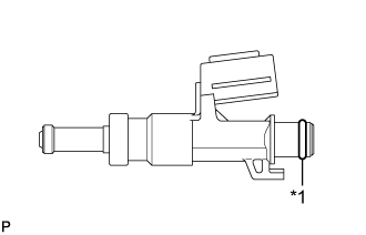
Remove the O-ring from the fuel injector assembly.
Text in Illustration*1
| O-Ring
|
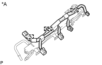
Detach the 3 clamps and then remove the No. 6 wire harness from the delivery pipe sub-assembly RH.
Text in Illustration*A
| Fuel Delivery Pipe sub-assembly RH
|
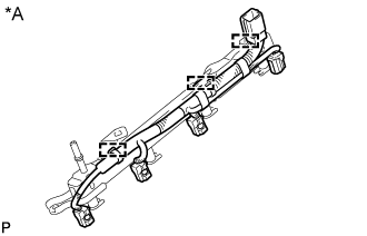
Detach the 3 clamps and then remove the No. 7 wire harness from the delivery pipe sub-assembly LH.
Text in Illustration*A
| Fuel Delivery Pipe sub-assembly LH
|