Впускной Коллектор -- Установка |
| 1. INSTALL INTAKE MANIFOLD |
Install a new gasket to the cylinder head with the protrusion facing upward.
Text in Illustration *a Protrusion *b Upward
 |
Install the intake manifold with the 6 bolts and 2 nuts. Uniformly tighten the bolts and nuts in several steps.
- Момент затяжки:
- 24 N*m{240 kgf*cm, 17 ft.*lbf}
Text in Illustration *1 Nut
 |
Install the wire harness bracket with the bolt.
- Момент затяжки:
- 13 N*m{131 kgf*cm, 9 ft.*lbf}
| 2. INSTALL INJECTION PIPE |
Install the 2 lower clamps to the intake manifold.
Using a 17 mm union nut wrench, install the 4 injection pipes.
- Момент затяжки:
- 25 N*m{250 kgf*cm, 18 ft.*lbf}
- ПРИМЕЧАНИЕ:
- Use the formula to calculate special torque values for situations where a union nut wrench is combined with a torque wrench (See page Нажмите здесь).
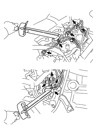 |
Secure the injection pipes by installing the 2 upper pipe clamps and 2 nuts.
- Момент затяжки:
- 5.0 N*m{51 kgf*cm, 44 in.*lbf}
| 3. INSTALL DIESEL THROTTLE BODY ASSEMBLY |
Install a new gasket and the diesel throttle body.
Connect the throttle control motor connector.
Install the bracket with the 2 bolts.
- Момент затяжки:
- 13 N*m{131 kgf*cm, 9 ft.*lbf}
Connect the throttle open switch connector.
| 4. INSTALL INTAKE FLANGE |
Install a new gasket and the intake flange with the 3 nuts.
- Момент затяжки:
- 12 N*m{122 kgf*cm, 9 ft.*lbf}
Connect the manifold absolute pressure sensor connector.
Install the heater hose bracket with the bolt.
- Момент затяжки:
- 14 N*m{138 kgf*cm, 10 ft.*lbf}
Connect the PCV hose.
| 5. INSTALL INTAKE PIPE |
Install the intake pipe with the 2 bolts.
- Момент затяжки:
- 18 N*m{184 kgf*cm, 13 ft.*lbf}
Tighten the intake pipe clamp.
- Момент затяжки:
- 6.0 N*m{61 kgf*cm, 53 in.*lbf}
| 6. BLEED INJECTION PIPE |
Install the 2 lower clamps to the intake manifold.
Install the 4 injection pipes.
- Момент затяжки:
- 25 N*m{250 kgf*cm, 18 ft.*lbf}
Text in Illustration *a for Injection Nozzle Side *b for Injection Pump Side - ПРИМЕЧАНИЕ:
- Use the formula to calculate special torque values for situations where a union nut wrench is combined with a torque wrench (See page Нажмите здесь).
 |
Install the 2 upper pipe clamps with the 2 nuts.
- Момент затяжки:
- 5.0 N*m{51 kgf*cm, 44 in.*lbf}
| 7. INSPECT FOR FUEL LEAK |
Check that there are no fuel leaks anywhere in the fuel system after performing maintenance.
- УКАЗАНИЕ:
- When checking for fuel leaks, make sure that there is pressure in the fuel line.