Power Source Network. Hilux. Tgn26, 36 Kun25, 26, 35, 36 Ggn25
Networking. Hilux. Tgn26, 36 Kun25, 26, 35, 36 Ggn25
CHECK HARNESS AND CONNECTOR (ECM - BATTERY AND BODY GROUND)
CAN COMMUNICATION SYSTEM (w/ VSC) - ECM Communication Stop Mode |
DESCRIPTION
| Detection Item | Symptom | Trouble Area |
| ECM Communication Stop Mode | Either condition is met:
|
|
WIRING DIAGRAM
INSPECTION PROCEDURE
- NOTICE:
- Inspect the fuses for circuits related to this system before performing the following inspection procedure.
| 1.CHECK HARNESS AND CONNECTOR (ECM - BATTERY AND BODY GROUND) |
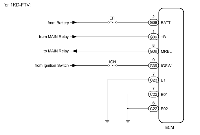
for 1KD-FTV:
Disconnect the C22, C23, G38 and G39 ECM connectors.
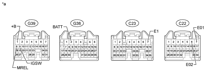
Text in Illustration *a Front view of wire harness connector
(to ECM)- - Measure the voltage according to the value(s) in the table below.
- Standard Voltage:
Tester Connection Condition Specified Condition G38-2 (BATT) - Body ground Always 11 to 14 V G39-1 (+B) - Body ground Battery positive (+) voltage applied to terminal G39-8 (MREL) 11 to 14 V G39-9 (IGSW) - Body ground Ignition switch ON 11 to 14 V
Measure the resistance according to the value(s) in the table below.
- Standard Resistance:
Tester Connection Condition Specified Condition C23-7 (E1) - Body ground Always Below 1 Ω C22-7 (E01) - Body ground Always Below 1 Ω C22-6 (E02) - Body ground Always Below 1 Ω
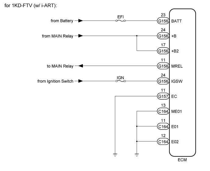
for 1KD-FTV (w/ i-ART):
Disconnect the C164, G156 and G157 ECM connectors.

Text in Illustration *a Front view of wire harness connector
(to ECM)- - Measure the voltage according to the value(s) in the table below.
- Standard Voltage:
Tester Connection Condition Specified Condition G157-23 (BATT) - Body ground Always 11 to 14 V G157-24 (+B) - Body ground Battery positive (+) voltage applied to terminal G156-11 (MREL) 11 to 14 V G157-17 (+B2) - Body ground Battery positive (+) voltage applied to terminal G156-11 (MREL) 11 to 14 V G156-24 (IGSW) - Body ground Ignition switch ON 11 to 14 V
Measure the resistance according to the value(s) in the table below.
- Standard Resistance:
Tester Connection Condition Specified Condition G157-11 (EC1) - Body ground Always Below 1 Ω C164-13 (ME01) - Body ground Always Below 1 Ω C164-11 (E01) - Body ground Always Below 1 Ω C164-12 (E02) - Body ground Always Below 1 Ω
|
| ||||
| OK | ||
| ||