Audio And Visual System (For Radio And Display Type) Microphone Circuit Between Microphone And Radio Receiver
DESCRIPTION
WIRING DIAGRAM
INSPECTION PROCEDURE
CHECK MICROPHONE (OPERATION CHECK)
CHECK HARNESS AND CONNECTOR (RADIO AND DISPLAY RECEIVER - MAP LIGHT)
CHECK RADIO AND DISPLAY RECEIVER ASSEMBLY
REPLACE TELEPHONE MICROPHONE WITH ANOTHER AND CHECK
AUDIO AND VISUAL SYSTEM (for Radio and Display Type) - Microphone Circuit between Microphone and Radio Receiver |
DESCRIPTION
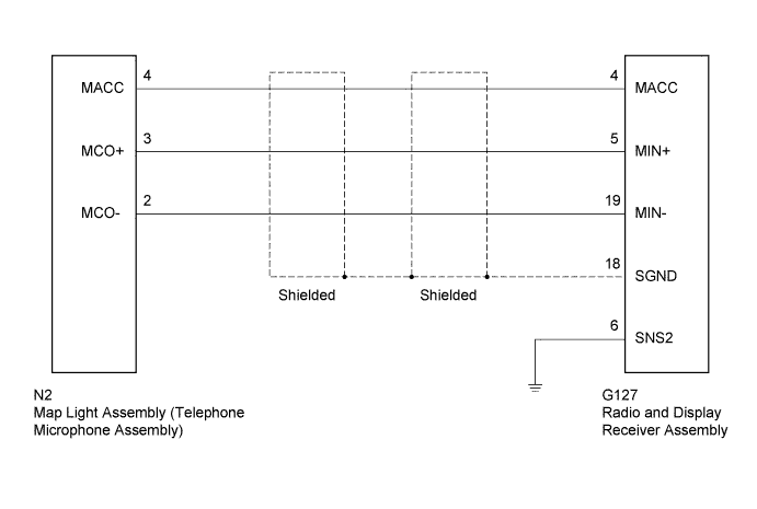
Microphone signal from the telephone microphone assembly is sent to the radio and display receiver assembly. Also, power is supplied from the radio and display receiver assembly to the telephone microphone assembly.
WIRING DIAGRAM
INSPECTION PROCEDURE
| 1.CHECK MICROPHONE (OPERATION CHECK) |
Enter the "Microphone & Voice Recognition Check" screen (HILUX_TGN26 RM0000043X901QX.html).
When voice is input into the microphone, check that the microphone input level meter changes according to the input voice.
- OK:
- Check result is normal.
| 2.CHECK HARNESS AND CONNECTOR (RADIO AND DISPLAY RECEIVER - MAP LIGHT) |
Disconnect the G127 radio and display receiver assembly connector.
Disconnect the N2 map light assembly connector.
Measure the resistance according to the value(s) in the table below.
- Standard Resistance:
Tester Connection
| Condition
| Specified Condition
|
G127-4 (MACC) - N2-4 (MACC)
| Always
| Below 1 Ω
|
G127-5 (MIN+) - N2-3 (MCO+)
|
G127-19 (MIN-) - N2-2 (MCO-)
|
G127-6 (SNS2) - Body ground
|
G127-4 (MACC) - Body ground
| Always
| 10 kΩ or higher
|
G127-5 (MIN+) - Body ground
|
G127-19 (MIN-) - Body ground
|
G127-18 (SGND) - Body ground
|
| | REPAIR OR REPLACE HARNESS OR CONNECTOR |
|
|
| 3.CHECK RADIO AND DISPLAY RECEIVER ASSEMBLY |
Measure the resistance according to the value(s) in the table below.
- Standard Resistance:
Tester Connection
| Condition
| Specified Condition
|
G127-18 (SGND) - Body ground
| Always
| Below 1 Ω
|
G127-19 (MIN-) - Body ground
|
Measure the voltage according to the value(s) in the table below.
- Standard Voltage:
Tester Connection
| Switch Condition
| Specified Condition
|
G127-4 (MACC) - Body ground
| Ignition switch ACC
| 4 to 6 V
|
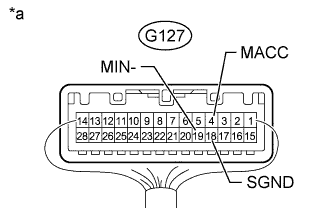
Text in Illustration*a
| Component with harness connected
(Radio and Display Receiver Assembly)
|
| 4.REPLACE TELEPHONE MICROPHONE WITH ANOTHER AND CHECK |
Replace the telephone microphone with a normal one (HILUX_TGN26 RM000002LJJ028X.html).
Check if the same problem occurs again.
- OK:
- Malfunction disappears.
| OK |
|
|
|
| END (TELEPHONE MICROPHONE ASSEMBLY IS DEFECTIVE) |
|