Engine Assembly -- Installation |
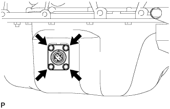
| 1. INSTALL ENGINE OIL LEVEL SENSOR |
Install the level sensor with the 4 bolts.
- Момент затяжки:
- 7.0 Н*м{71 кгс*см, 62 фунт-сила-дюймов}
 |
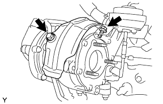
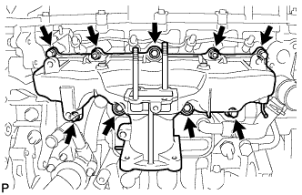
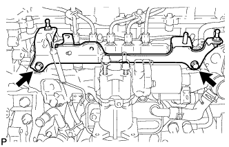
| 2. INSTALL EXHAUST MANIFOLD |
Loosely install the 2 collars of the exhaust manifold with the nuts labeled A. Tighten the nuts until the contact surface of the exhaust manifold contacts with the cylinder head.
 |
Loosely install the 6 collars with the 6 nuts.
- УКАЗАНИЕ:
- When installing the collars, pay attention to the mounting orientation. Ring groove of the collar should be outside. Refer to the illustration.
- Tighten the nuts so that the position of the exhaust manifold can be adjusted in a later step.
Install a new gasket and the turbocharger with the 3 nuts.
- Момент затяжки:
- 60 Н*м{612 кгс*см, 44 фунт-сила-футов}
 |
Install the turbocharger stay with the 2 nuts and 2 spacers.
- Момент затяжки:
- 36 Н*м{367 кгс*см, 27 фунт-сила-футов}
- УКАЗАНИЕ:
- Do not reuse the turbocharger stay.
 |
Tighten the 8 nuts.
- Момент затяжки:
- 47 Н*м{479 кгс*см, 35 фунт-сила-футов}
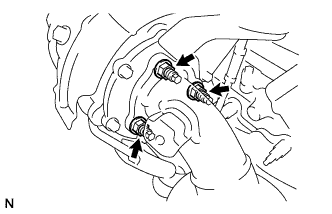
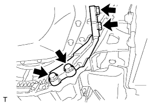
| 3. INSTALL NO. 2 TURBO OIL PIPE |
 |
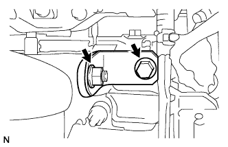
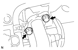
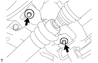
Tighten the turbo oil pipe with the 2 bolts.
- Момент затяжки:
- 35 Н*м{357 кгс*см, 26 фунт-сила-футов}
Connect the 2 vacuum hoses.
 |
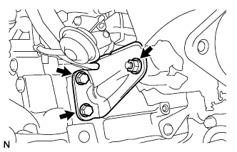
| 4. INSTALL EGR COOLER ASSEMBLY |
Temporarily assemble 2 new gaskets, the No. 2 EGR valve, No. 1 EGR pipe and EGR cooler with the 2 bolts and 2 nuts.
 |
Install a new O-ring to the EGR cooler.
Install a new gasket to the No. 1 EGR pipe.
Install a new gasket to the EGR cooler.
Temporarily install the EGR cooler with the 2 bolts and 2 nuts.
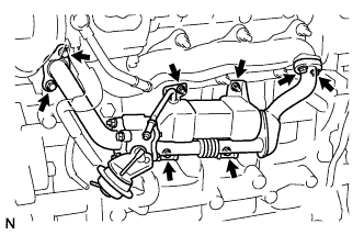 |
Temporarily install the 4 bolts.
Tighten the 2 bolts and 2 nuts holding the EGR cooler to the cylinder block.
- Момент затяжки:
- 10 Н*м{102 кгс*см, 7 фунт-сила-футов}
 |
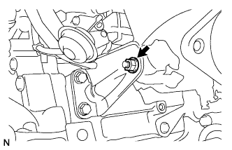
Tighten the 2 bolts holding the EGR cooler to the exhaust manifold.
- Момент затяжки:
- 16 Н*м{163 кгс*см, 12 фунт-сила-футов}
 |
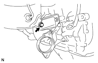
Tighten the 2 bolts holding the EGR cooler to the cylinder head.
- Момент затяжки:
- 24 Н*м{245 кгс*см, 18 фунт-сила-футов}
 |
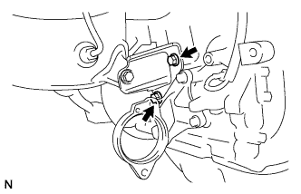
Tighten the 2 bolts and 2 nuts holding the EGR pipe to the EGR valve.
- Момент затяжки:
- 21 Н*м{241 кгс*см, 15 фунт-сила-футов}
 |
Connect the vacuum hose.
 |
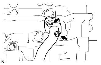
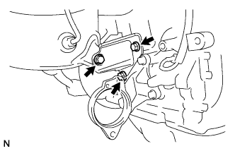
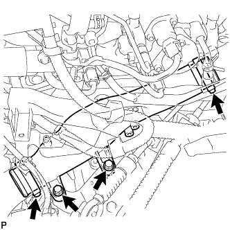
| 5. INSTALL TURBO OIL OUTLET PIPE |
 |
Install 2 new gaskets and the oil pipe with the 4 bolts.
- Момент затяжки:
- 11 Н*м{112 кгс*см, 8 фунт-сила-футов}
| 6. INSTALL NO. 5 WATER BY-PASS PIPE |
| 7. INSTALL NO. 1 TURBO INSULATOR |
 |
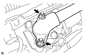
Install the insulator with the 2 bolts.
- Момент затяжки:
- 20.5 Н*м{209 кгс*см, 15 фунт-сила-футов}
| 8. INSTALL EXHAUST MANIFOLD CONVERTER SUB-ASSEMBLY |
Temporarily install a new turbine outlet elbow gasket and exhaust manifold converter with the 3 nuts.
 |
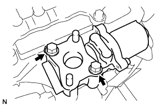
Temporarily install the No. 2 exhaust manifold stay with the 2 bolts and nut.
 |
Temporarily install the No. 2 manifold stay with the 3 bolts.
 |
Temporarily install the No. 1 manifold stay with the bolt and nut.
 |
Tighten the 2 bolts of the No. 2 exhaust manifold stay to the cylinder block (Upper bolt → Lower bolt).
- Момент затяжки:
- 56 Н*м{571 кгс*см, 41 фунт-сила-футов}
 |
Tighten the 3 nuts of the exhaust manifold converter to the turbocharger sub-assembly (While pushing manifold converter towards turbocharger sub-assembly).
- Момент затяжки:
- 25 Н*м{255 кгс*см, 18 фунт-сила-футов}
|
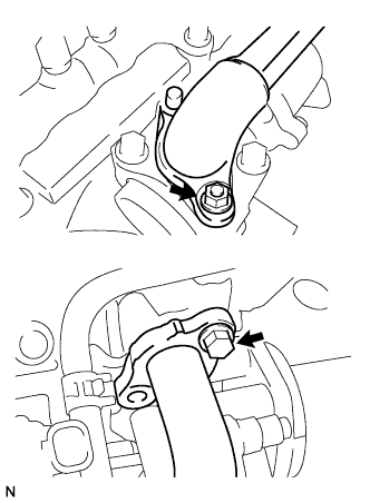
Tighten the nut of the No. 2 exhaust manifold stay to the exhaust manifold converter.
- Момент затяжки:
- 56 Н*м{571 кгс*см, 41 фунт-сила-футов}
 |
Tighten the bolt of the No. 2 manifold stay to the exhaust manifold converter.
- Момент затяжки:
- 56 Н*м{571 кгс*см, 41 фунт-сила-футов}
- УКАЗАНИЕ:
- Ensure stay pushed flush to cylinder block and manifold converter while tightening.
 |
Tighten the 2 bolts of the No. 2 manifold stay to the cylinder block.
- Момент затяжки:
- 56 Н*м{571 кгс*см, 41 фунт-сила-футов}
 |
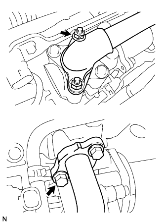
Tighten the bolt of the No. 1 manifold stay to the cylinder head.
- Момент затяжки:
- 25 Н*м{255 кгс*см, 18 фунт-сила-футов}
- УКАЗАНИЕ:
- Ensure stay pushed flush to cylinder head and manifold converter while tightening.
 |
Tighten the nut of the No. 1 manifold stay to the exhaust manifold converter.
- Момент затяжки:
- 25 Н*м{255 кгс*см, 18 фунт-сила-футов}
 |
| 9. INSTALL NO. 1 MANIFOLD CONVERTER INSULATOR |
Install the No. 1 manifold converter insulator with the 5 bolts.
- Момент затяжки:
- 29 Н*м{291 кгс*см, 21 фунт-сила-футов}
 |
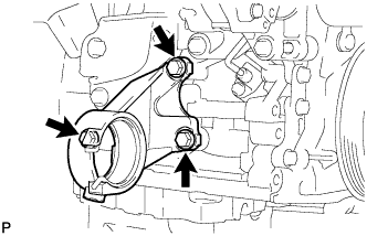
| 10. INSTALL DRIVE SHAFT BEARING BRACKET |
Install the bearing bracket with the 3 bolts.
- Момент затяжки:
- 64 Н*м{653 кгс*см, 47 фунт-сила-футов}
 |
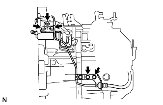
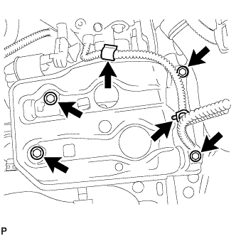
| 11. INSTALL GLOW PLUG ASSEMBLY |
Install the 4 glow plugs.
- Момент затяжки:
- 12.3 Н*м{125 кгс*см, 9 фунт-сила-футов}
 |
Install the glow plug connector with the 5 nuts.
- Момент затяжки:
- 2.2 Н*м{22 кгс*см, 19 фунт-сила-дюймов}for glow plug connector
- 4.0 Н*м{41 кгс*см, 35 фунт-сила-дюймов}for wire harness
Install the 5 grommets.
| 12. INSTALL WATER INLET HOUSING |
Install a new gasket and the inlet housing with the 3 nuts.
- Момент затяжки:
- 9.0 Н*м{92 кгс*см, 80 фунт-сила-дюймов}
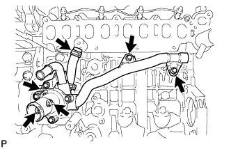 |
Connect the hose.
Install a new O-ring and the by-pass pipe with the 2 bolts.
- Момент затяжки:
- 11 Н*м{112 кгс*см, 8 фунт-сила-футов}
| 13. INSTALL NO. 1 OIL COOLER BRACKET |
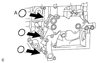 |
Apply engine oil to 2 new O-rings.
- ПРИМЕЧАНИЕ:
- Do not apply engine oil to the O-ring labeled A.
Install the 3 O-rings to the oil cooler bracket.
Install the oil cooler bracket with the 6 bolts and nut.
- Момент затяжки:
- 11 Н*м{112 кгс*см, 8 фунт-сила-футов}
- УКАЗАНИЕ:
- Each bolt length is indicated below.
- Bolt length:
- 36 mm (1.42 in.) for bolt A
- 49 mm (1.93 in.) for except bolt A
 |
| 14. INSTALL NO. 1 TURBO OIL PIPE |
Install the oil pipe and 2 new gaskets with the 2 union bolts.
- Момент затяжки:
- 35 Н*м{357 кгс*см, 26 фунт-сила-футов}
- УКАЗАНИЕ:
- Be sure to install the union bolt A so that the gasket is positioned as shown in the illustration.
 |
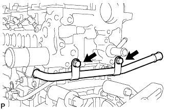
| 15. INSTALL NO. 3 WATER BY-PASS PIPE |
Install a new O-ring and the by-pass pipe with the 2 bolts.
- Момент затяжки:
- 21 Н*м{214 кгс*см, 15 фунт-сила-футов}
 |
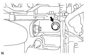
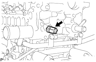
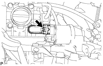
| 16. INSTALL DIESEL ENGINE COOLANT TEMPERATURE SENSOR |
Install a new gasket and the sensor.
- Момент затяжки:
- 19.6 Н*м{200 кгс*см, 14 фунт-сила-футов}
 |
| 17. INSTALL OIL COOLER |
Install 3 new O-rings and the oil cooler with the 5 bolts.
- Момент затяжки:
- 11 Н*м{112 кгс*см, 8 фунт-сила-футов}
 |
Install the by-pass hose and position the 2 clips.
Connect the oil pressure switch connector.
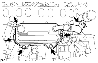
| 18. INSTALL INTAKE MANIFOLD |
Install a new gasket and the intake manifold with the 7 bolts and 2 nuts.
- Момент затяжки:
- 26 Н*м{265 кгс*см, 19 фунт-сила-футов}
 |
| 19. INSTALL DIESEL THROTTLE BODY |
Install a new gasket and the diesel throttle body with the 2 nuts and 2 bolts.
- Момент затяжки:
- 21 Н*м{214 кгс*см, 15 фунт-сила-футов}
 |
Connect the throttle position sensor connector.
Connect the throttle motor connector.
| 20. INSTALL INJECTOR ASSEMBLY |
Install the injector (see page RAV4_ACA30 RM0000015BN002X.html).
| 21. INSTALL COMMON RAIL ASSEMBLY |
Install the common rail (see page RAV4_ACA30 RM0000015BV002X.html).
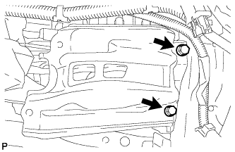
| 22. INSTALL ENGINE COVER BRACKET |
Install the cover bracket with the 2 bolts.
- Момент затяжки:
- 20 Н*м{204 кгс*см, 15 фунт-сила-футов}
 |
Install the pressure sensor with the bolt.
- Момент затяжки:
- 8.8 Н*м{90 кгс*см, 78 фунт-сила-дюймов}
| 23. INSTALL EGR VALVE ASSEMBLY |
Install a new gasket and the EGR valve with the 2 bolts.
- Момент затяжки:
- 24 Н*м{245 кгс*см, 18 фунт-сила-футов}
 |
Connect the EGR valve connector.
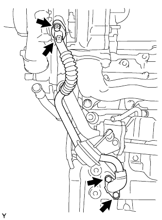
| 24. INSTALL NO. 2 EGR PIPE SUB-ASSEMBLY |
Temporarily install 2 new gaskets and the EGR pipe with the nut and bolt.
 |
Temporarily install the bolt and nut.
 |
Tighten the 2 bolts holding the EGR pipe to the cylinder head.
- Момент затяжки:
- 24 Н*м{245 кгс*см, 18 фунт-сила-футов}
 |
Tighten the 2 nuts holding the EGR pipe to the EGR valve.
- Момент затяжки:
- 24 Н*м{245 кгс*см, 18 фунт-сила-футов}
 |
| 25. INSTALL OIL DIPSTICK GUIDE |
Install a new O-ring to the dipstick guide.
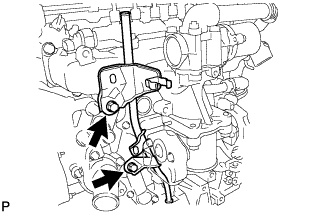
Install the dipstick guide with the 2 bolts.
- Момент затяжки:
- 33 Н*м{337 кгс*см, 24 фунт-сила-футов}
 |
| 26. INSTALL INJECTION OR SUPPLY PUMP ASSEMBLY |
Install the supply pump (see page RAV4_ACA30 RM0000015BY002X.html).
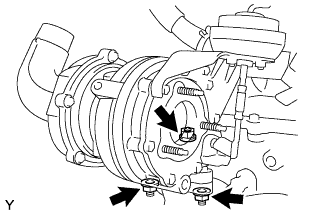
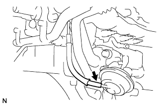
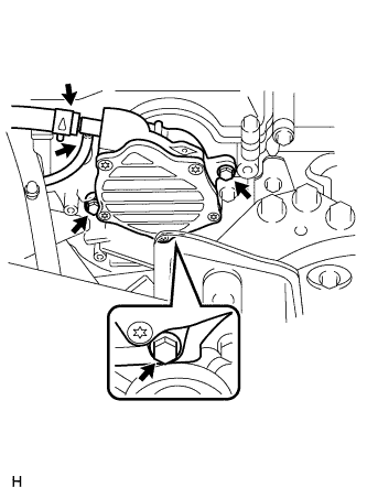
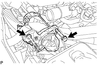
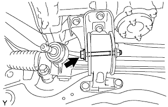
| 27. INSTALL VACUUM PUMP ASSEMBLY |
Нанесите моторное масло на маслопровод на кончике вакуумного насоса.
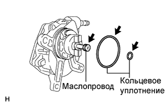 |
Нанесите моторное масло на два новых кольцевых уплотнения и установите их в вакуумный насос.
Установите вакуумный насос таким образом, чтобы соединительный зубец A вакуумного насоса вошел в зацепление с канавкой B распределительного вала.
 |
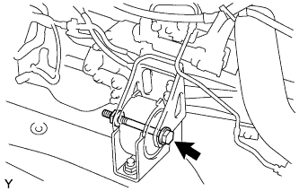
Вверните 3 новых фланцевых болта.
- Момент затяжки:
- 21 Н*м{214 кгс*см, 15 фунт-сила-футов}
 |
Подсоедините 2 вакуумных шланга.
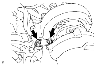
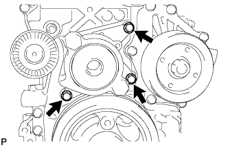
| 28. INSTALL V-RIBBED BELT TENSIONER ASSEMBLY |
Install the tensioner with the 3 bolts.
- Момент затяжки:
- 20 Н*м{204 кгс*см, 15 фунт-сила-футов}
 |
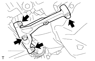
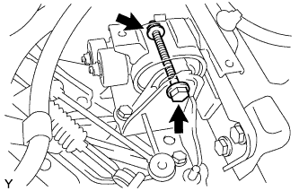
| 29. INSTALL TRANSVERSE ENGINE MOUNTING BRACKET |
Set the mounting bracket.
Temporarily tighten the 2 bolts (B) and 2 nuts.
 |
Tighten the 2 bolts (A).
- Момент затяжки:
- 28 Н*м{286 кгс*см, 21 фунт-сила-футов}for bolt A
Tighten the 2 bolts (B) and 2 nuts.
- Момент затяжки:
- 80 Н*м{816 кгс*см, 59 фунт-сила-футов}for bolt B, nut
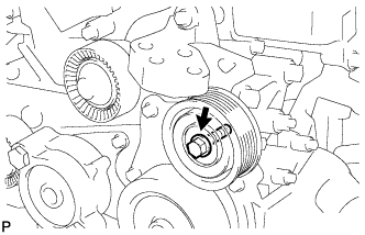
| 30. INSTALL NO. 1 IDLER PULLEY ASSEMBLY |
Install the idler pulley with the bolt.
- Момент затяжки:
- 40 Н*м{408 кгс*см, 30 фунт-сила-футов}
 |
Install the idler pulley cover plate.
| 31. INSTALL NO. 2 IDLER PULLEY SUB-ASSEMBLY |
Install the idler pulley with the bolt.
- Момент затяжки:
- 40 Н*м{408 кгс*см, 30 фунт-сила-футов}
 |
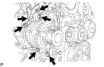
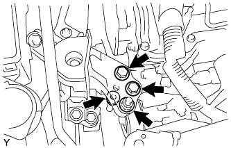
| 32. INSTALL GENERATOR ASSEMBLY |
Install the generator with the 3 bolts.
- Момент затяжки:
- 25 Н*м{255 кгс*см, 18 фунт-сила-футов}
- ПРИМЕЧАНИЕ:
- Be careful that the wire harness of the crankshaft position sensor does not get caught between the cylinder block and generator when installing the generator.
 |
Connect the generator wire with the nut and bolt.
- Момент затяжки:
- 9.8 Н*м{100 кгс*см, 87 фунт-сила-дюймов}for nut
- 7.7 Н*м{79 кгс*см, 68 фунт-сила-дюймов}for bolt
Install the terminal cap.
Connect the generator connector.
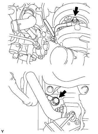
| 33. INSTALL COMPRESSOR WITH PULLEY ASSEMBLY |
Без шпильки:
Установите компрессор системы кондиционирования и закрепите его 4 болтами.- Момент затяжки:
- 25 Н*м{255 кгс*см, 18 фунт-сила-футов}
- ПРИМЕЧАНИЕ:
- При установке компрессора системы кондиционирования затягивайте болты в последовательности, показанной на рисунке.
 |
При наличии шпильки:
Установите компрессор системы кондиционирования и закрепите его 3 болтами и гайкой.- Момент затяжки:
- 25 Н*м{255 кгс*см, 18 фунт-сила-футов}
- ПРИМЕЧАНИЕ:
- При установке компрессора системы кондиционирования затягивайте болты в последовательности, показанной на рисунке.
Подсоедините разъем.
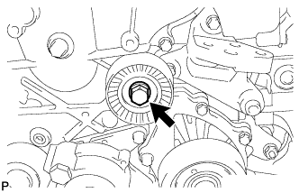
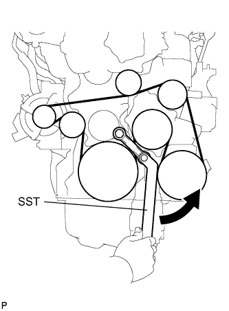
| 34. INSTALL FAN AND GENERATOR V BELT |
Using SST and 22 mm wrench, rotate the tensioner pulley counterclockwise, and then install the V-ribbed belt.
- Специальный инструмент (SST):
- 09216-42010
- ПРИМЕЧАНИЕ:
- Make sure that the V-ribbed belt is set properly at each pulley.
- Make sure SST is installed as shown in the illustration. If not, SST and/or the V-ribbed belt may not be able to be removed.
 |
| 35. REMOVE ENGINE STAND |
Install a sling device and chain block.
Remove the engine stand.
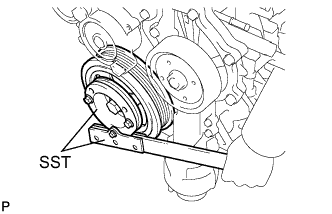
| 36. INSTALL FLYWHEEL SUB-ASSEMBLY |
Hold the crankshaft with SST.
- Специальный инструмент (SST):
- 09213-58013
09330-00021
 |
Using several steps, install and tighten 8 new bolts with a T55 "torx" socket wrench uniformly in the sequence shown in the illustration.
- УКАЗАНИЕ:
- Do not reuse the flywheel installation bolts.
- Be sure to check the tightening torque within 5 minutes after tightening.
- Do not impact or damage the flywheel installation bolts. Be sure to handle them carefully.
- Make sure that the seating surface of the flywheel installation bolts and the installation surfaces of the crankshaft and flywheel are free from oil or foreign matter.
- Момент затяжки:
- 70.5 Н*м{719 кгс*см, 52 фунт-сила-футов}
 |
| 37. INSTALL CLUTCH DISC ASSEMBLY |
Вставьте SST в ведомый диск сцепления, а затем – в маховик.
- Специальный инструмент (SST):
- 09301-00220
- ПРИМЕЧАНИЕ:
- Следите за тем, чтобы ведомый диск сцепления был вставлен правильной стороной.
 |
| 38. INSTALL CLUTCH COVER ASSEMBLY |
Совместите сборочные метки кожуха сцепления и маховика.
 |
Равномерно затяните 6 болтов в последовательности, показанной на рисунке, начиная с болта, который расположен сверху около штифта.
- Момент затяжки:
- 19 Н*м{195 кгс*см, 14 фунт-сила-футов}
- ПРИМЕЧАНИЕ:
- Равномерно затягивайте болты в последовательности, показанной на рисунке, поворачивая каждый болт на 180° за одну операцию.
- Проверьте, чтобы диск располагался по центру, а затем, осторожно перемещая SST вверх-вниз и вправо-влево, затяните болты.
| 39. INSTALL MANUAL TRANSAXLE ASSEMBLY |
 |
Align the input shaft with the clutch disc and install the transaxle to the engine.
Install the 10 bolts.
- Момент затяжки:
- 46 Н*м{469 кгс*см, 34 фунт-сила-футов} for bolt A
- 64 Н*м{653 кгс*см, 47 фунт-сила-футов} for bolt B
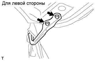
| 40. INSTALL STIFFENER PLATE LH |
 |
Install the stiffener plate with the 4 bolts.
- Момент затяжки:
- 46 Н*м{469 кгс*см, 34 фунт-сила-футов}
| 41. INSTALL STIFFENER PLATE RH |
 |
Install the stiffener plate with the 4 bolts.
- Момент затяжки:
- 46 Н*м{469 кгс*см, 34 фунт-сила-футов}
| 42. INSTALL OIL PAN INSULATOR |
| 43. INSTALL STARTER ASSEMBLY |
Install the starter with the 2 bolts.
- Момент затяжки:
- 64 Н*м{652 кгс*см, 47 фунт-сила-футов}
 |
Install the terminal nut and cover the nut with the cap.
- Момент затяжки:
- 9.8 Н*м{100 кгс*см, 7 фунт-сила-футов}
 |
Connect the starter connector.
 |
| 44. INSTALL ENGINE WIRE |
Install the engine wire to the engine.
| 45. INSTALL NO. 1 AIR TUBE |
Install the air tube with the 2 bolts.
- Момент затяжки:
- 29 Н*м{296 кгс*см, 21 фунт-сила-футов}
 |
Tighten the 2 clamps.
- Момент затяжки:
- 6.3 Н*м{64 кгс*см, 56 фунт-сила-дюймов}
Install the wire harness with the 2 bolts.
- Момент затяжки:
- 7.5 Н*м{76 кгс*см, 66 фунт-сила-дюймов}
 |
| 46. INSTALL FRONT SUSPENSION CROSSMEMBER SUB-ASSEMBLY |
Attach the engine together with the transaxle to the suspension crossmember and mounting.
Install the bolt which secures the engine mounting bracket to the mounting insulator.
- Момент затяжки:
- 95 Н*м{969 кгс*см, 70 фунт-сила-футов}
 |
| 47. INSTALL FRONT CROSS MEMBER SUB-ASSEMBLY |
Install the bolt and nut which secures the engine mounting bracket to the mounting insulator.
- Момент затяжки:
- 145 Н*м{1,479 кгс*см, 107 фунт-сила-футов}
 |
| 48. INSTALL ENGINE WITH TRANSAXLE |
Place the engine on an engine lifter.
- УКАЗАНИЕ:
- Place the engine on wooden blocks or equivalent so that the engine is level.
Using the chain block, slowly install the engine to the vehicle and the intermediate shaft to the pinion.
- ПРЕДОСТЕРЕЖЕНИЕ:
- Do not raise the engine more than necessary. If the engine is raised excessively, the vehicle may also be lifted up.
- ПРИМЕЧАНИЕ:
- Make sure that the engine is clear of all wiring and hoses.
- While raising the engine into the vehicle, do not allow it to contact the vehicle.
- Align the matchmarks on the intermediate shaft and pinion.
Temporarily install the suspension member, crossmember with the 10 bolts.
 |
Temporarily install the member brace rear RH and LH with the 6 bolts.
Install the engine mounting insulator LH with the bolt and nut.
- Момент затяжки:
- 56 Н*м{571 кгс*см, 41 фунт-сила-футов}
- ПРИМЕЧАНИЕ:
- While holding the bolt in place, tighten the nut.
 |
Install the engine mounting insulator RH with the 2 bolts and 2 nuts.
- Момент затяжки:
- 95 Н*м{969 кгс*см, 70 фунт-сила-футов}for bolt, nut A
- 52 Н*м{530 кгс*см, 38 фунт-сила-футов}for nut
 |
Tighten the suspension member and crossmember's bolts.
- Момент затяжки:
- 96 Н*м{979 кгс*см, 71 фунт-сила-футов}for bolt A
- 145 Н*м{1,478 кгс*см, 107 фунт-сила-футов}for bolt B
 |
Tighten the member brace rear's bolts.
- Момент затяжки:
- 145 Н*м{1,478 кгс*см, 107 фунт-сила-футов}for bolt C
- 93 Н*м{948 кгс*см, 69 фунт-сила-футов}for bolt D
Remove the sling device and chain block.
Remove the 2 bolts and No. 1 and No. 2 engine hangers.
| 49. INSTALL FRONT DRIVE SHAFT LH |
Install the drive shaft (see page RAV4_ACA30 RM00000226O000X.html).
| 50. INSTALL FRONT DRIVE SHAFT RH |
Install the drive shaft (see page RAV4_ACA30 RM00000226O000X.html).
| 51. CONNECT TIE ROD END SUB-ASSEMBLY LH |
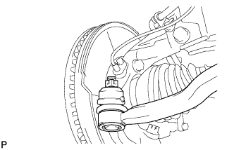 |
Установите наконечник рулевой тяги на поворотный кулак и закрепите его корончатой гайкой.
- Момент затяжки:
- 49 Н*м{500 кгс*см, 36 фунт-сила-футов}
- ПРИМЕЧАНИЕ:
- Если отверстия фиксатора не совпадают, доверните гайку еще на 60°.
Установите новый шплинт.
| 52. CONNECT TIE ROD END SUB-ASSEMBLY RH |
- УКАЗАНИЕ:
- Порядок выполнения работ для правой и левой сторон одинаков.
| 53. CONNECT STEERING INTERMEDIATE SHAFT |
 |
Совместите сборочные метки и установите промежуточный вал на рулевой механизм.
- Момент затяжки:
- 35 Н*м{360 кгс*см, 26 фунт-сила-футов}
| 54. CONNECT FRONT STABILIZER LINK ASSEMBLY LH |
Установите стойку и закрепите ее 2 гайками.
- Момент затяжки:
- 74 Н*м{755 кгс*см, 55 фунт-сила-футов}
| 55. CONNECT FRONT STABILIZER LINK ASSEMBLY RH |
- УКАЗАНИЕ:
- Порядок выполнения работ такой же, как для левой стороны.
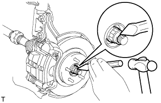
| 56. INSTALL FRONT AXLE HUB NUT LH |
Установите новую гайку крепления ступицы.
- Момент затяжки:
- 216 Н*м{2203 кгс*см, 159 фунт-сила-футов} Для φ 26
- 292 Н*м{2978 кгс*см, 215 фунт-сила-футов} Для φ 30
Накерните гайку крепления ступицы с помощью молотка и зубила.
 |
| 57. INSTALL FRONT AXLE HUB NUT RH |
| 58. INSTALL FRONT WHEELS |
| 59. INSTALL PROPELLER WITH CENTER BEARING SHAFT ASSEMBLY |
Совместите сборочные метки на раздаточной коробке и карданном валу.
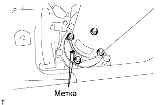 |
Установите карданный вал с центральным подшипником предварительно при помощи 4 гаек и 4 шайб.
Совместите сборочные метки на корпусе дифференциала и карданном валу.
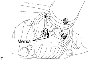 |
Установите карданный вал с центральным подшипником предварительно при помощи 4 гаек и 4 шайб.
Установите центральный опорный подшипник и шайбу центрального опорного подшипника при помощи 2 болтов предварительно.
 |
| 60. INSTALL FRONT EXHAUST PIPE ASSEMBLY |
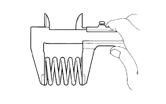
Using a vernier caliper, measure the free length of the compression spring.
- Minimum length:
- 41.5 mm (1.634 in.)
 |
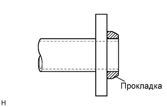
Install a new gasket by hand so that its surface is flush with the center exhaust manifold.
- ПРИМЕЧАНИЕ:
- Make sure the gasket is facing the correct direction.
- Do not reuse the removed gasket.
- Do not push in the gasket while installing the exhaust pipe.
 |
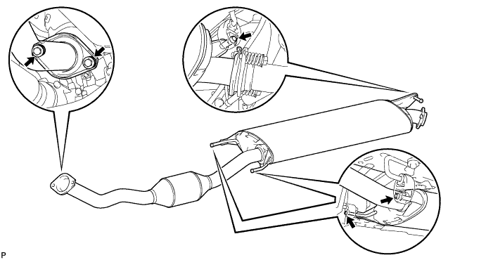
Connect the 3 exhaust pipe supports, and install the front exhaust pipe.
Install the 2 compression springs and 2 bolts.
- Момент затяжки:
- 43 Н*м{438 кгс*см, 32 фунт-сила-футов}
| 61. CONNECT CLUTCH RELEASE CYLINDER ASSEMBLY |
Connect the release cylinder and flexible hose bracket with the 5 bolts.
- Момент затяжки:
- 12 Н*м{122 кгс*см, 9 фунт-сила-футов}
 |
| 62. CONNECT TRANSMISSION CONTROL CABLE ASSEMBLY |
 |
Connect the ends of the control cable and install the 2 clips to the shift lever.
Turn the lock nuts of the shift cable 270° counterclockwise, and hold them in that position.
Install the shift cable while holding them.
Check that the cables are installed securely.
Push in the cable locks of the shift cable and select cable.
 |
Connect the cable ends of the control cable and install the 2 clips.
 |
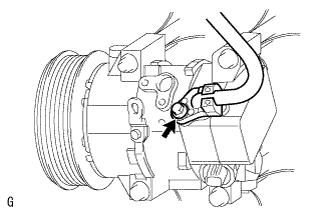
| 63. CONNECT SUCTION HOSE SUB-ASSEMBLY |
Снимите с трубопровода виниловую ленту.
 |
Нанесите необходимое количество компрессорного масла на новое кольцевое уплотнение и пригоночную поверхность компрессора системы кондиционирования.
- Компрессорное масло:
- ND-OIL 8 или аналог
Установите кольцевое уплотнение на трубопровод низкого давления кондиционера.
Установите трубопровод низкого давления кондиционера на компрессор системы кондиционирования и закрепите его болтом.
- Момент затяжки:
- 9,8 Н*м{100 кгс*см, 7 фунт-сила-футов}
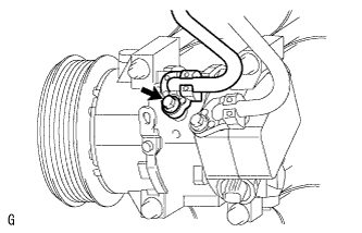
| 64. INSTALL DISCHARGE HOSE SUB-ASSEMBLY |
Install the discharge hose for compressor with the bolt.
- Момент затяжки:
- 9.8 Н*м{100 кгс*см, 7 фунт-сила-футов}
 |
| 65. INSTALL RADIATOR AND INTERCOOLER |
- ПРИМЕЧАНИЕ:
- When reusing the air hose or air tube, check that there is no damage and foreign objects. If necessary, clean it.
Align the intercooler with the radiator, and then install the intercooler to the radiator with the 4 bolts.
- Момент затяжки:
- 6.0 Н*м{61 кгс*см, 53 фунт-сила-дюймов}
 |
Install the No. 2 air tube to the intercooler and No. 3 air hose.
Install the bolt.
- Момент затяжки:
- 13 Н*м{133 кгс*см, 10 фунт-сила-футов}
Tighten the 2 clamps as shown in the illustration.
 |
Install the No. 2 air hose to the intercooler. Tighten the clamp as shown in the illustration.
 |
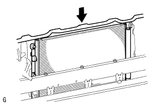
Install the radiator (with intercooler) to the vehicle.
Connect the No. 2 and No. 3 air hoses to the engine.
Tighten the 2 clamps as shown in the illustration.
 |
| 66. CONNECT OUTLET RADIATOR HOSE |
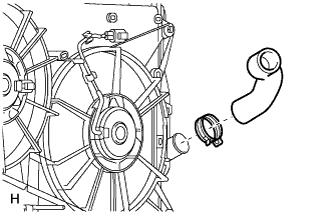 |
Install the outlet radiator hose to the radiator.
Position the clip as illustrated.
 |
| 67. CONNECT INLET RADIATOR HOSE |
 |
Install the inlet radiator hose and No. 5 water by-pass hose to the radiator.
Position clips A and B as illustrated.
 |
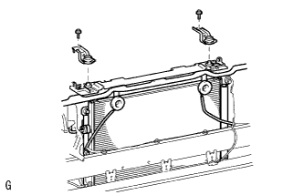
| 68. INSTALL RADIATOR SUPPORT UPPER |
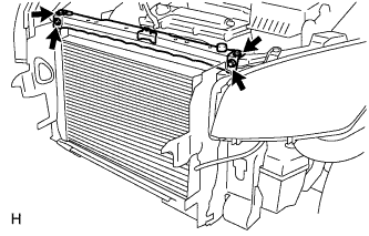 |
Install the radiator support upper with the 4 bolts.
- Момент затяжки:
- 29 Н*м{296 кгс*см, 21 фунт-сила-футов}
| 69. INSTALL HOOD LOCK ASSEMBLY |
Установите защелку замка капота и закрепите его 3 болтами.
- Момент затяжки:
- 8,0 Н*м{82 кгс*см, 71 фунт-сила-дюймов}
 |
| 70. INSTALL COOLER CONDENSER ASSEMBLY |
Установите конденсатор системы кондиционирования.
 |
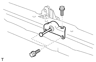
| 71. INSTALL RADIATOR SUPPORT UPPER BRACKET |
 |
Установите 2 кронштейна и закрепите их 2 болтами.
- Момент затяжки:
- 45 Н*м{459 кгс*см, 33 фунт-сила-футов}
| 72. INSTALL FRONT BUMPER REINFORCEMENT SUB-ASSEMBLY UPPER |
Установите усиление и закрепите его 2 болтами.
Присоедините 2 разъема звукового сигнала.
| 73. INSTALL FRONT BUMPER |
Install the front bumper (see page RAV4_ACA30 RM0000015RH003X.html).
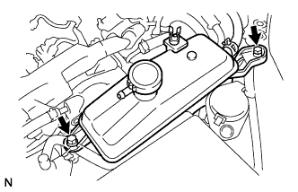
| 74. INSTALL RADIATOR RESERVE TANK ASSEMBLY |
Install the reservoir with the 2 bolts.
- Момент затяжки:
- 5.0 Н*м{51 кгс*см, 44 фунт-сила-дюймов}
 |
| 75. INSTALL ECM |
Install the 2 ECM brackets with the 4 screws.
- Момент затяжки:
- 3.0 Н*м{30 кгс*см, 27 фунт-сила-дюймов}
 |
Connect the 2 ECM connectors.
Connect the 2 connectors to the ECM and lower the 2 levers.
- ПРИМЕЧАНИЕ:
- Make sure that the 2 levers are securely lowered.
 |
Install the ECM with the 3 bolts.
- Момент затяжки:
- 6.5 Н*м{66 кгс*см, 57 фунт-сила-дюймов}
 |
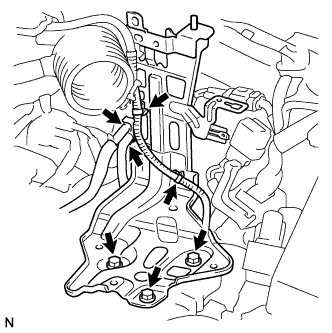
| 76. CONNECT HOSES AND CONNECTORS |
Install the vacuum switching valve bracket and vacuum transmitting pipe with the 3 bolts.
- Момент затяжки:
- 9.0 Н*м{92 кгс*см, 80 фунт-сила-дюймов}
Connect the 2 ECM connectors.
Connect the 2 heater hoses.
Connect the 2 fuel hoses.
Connect the vacuum pump hose.
Connect the 2 injector driver connectors.
Connect the starter wire with the nut.
- Момент затяжки:
- 9.8 Н*м{100 кгс*см, 7 фунт-сила-футов}
Connect the 3 connectors and wire with the nut.
- Момент затяжки:
- 12 Н*м{122 кгс*см, 9 фунт-сила-футов}
Install the engine room junction block cover (upper).
| 77. INSTALL AIR CLEANER BRACKET |
Install the bracket with the 3 bolts.
- Момент затяжки:
- 7.5 Н*м{76 кгс*см, 66 фунт-сила-дюймов}
 |
Connect the 2 fuel hoses to the bracket.
Attach the 2 wire harness clamps.
Install the glow plug relay and connect the fuel filter level switch connector.
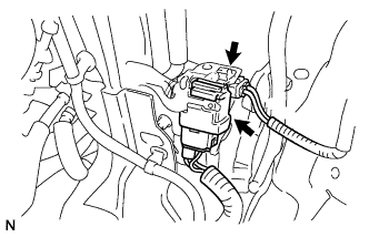 |
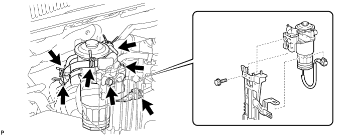
| 78. INSTALL FUEL FILTER ASSEMBLY |
Install the fuel filter with the bolt.
- Момент затяжки:
- 7.0 Н*м{71 кгс*см, 62 фунт-сила-дюймов}
Connect the 4 hoses.
Connect the level warning switch connector.
| 79. INSTALL AIR CLEANER CASE |
Install the cleaner case with the 3 bolts and connect the wire harness clamp.
- Момент затяжки:
- 5.0 Н*м{51 кгс*см, 44 фунт-сила-дюймов}
 |
Install the air cleaner element.
| 80. INSTALL AIR CLEANER CAP SUB-ASSEMBLY |
Insert the hinge parts of the air cleaner cap into the air cleaner case, and then hang the 3 hook clamps.
 |
Connect the mass air flow meter connector.
Engage the wire harness clamp.
| 81. INSTALL BATTERY BRACKET REINFORCEMENT |
Install the bracket reinforcement with the 2 bolts.
- Момент затяжки:
- 19 Н*м{194 кгс*см, 14 фунт-сила-футов}
 |
| 82. INSTALL FRONT BATTERY BRACKET |
Install the bracket front with the 4 bolts.
- Момент затяжки:
- 19 Н*м{194 кгс*см, 14 фунт-сила-футов}
 |
Attach the 2 wire harness clamps.
| 83. INSTALL BATTERY |
| 84. REMOVE BATTERY CLAMP SUB-ASSEMBLY |
Attach the hook of the battery clamp to the battery bracket front.
 |
Temporarily tighten the nut and install the bolt.
Adjust the battery clamp's position.
Fully tighten the nut and bolt.
- Момент затяжки:
- 5.0 Н*м{51 кгс*см, 44 фунт-сила-дюймов}
Attach the 2 wire harness clamps.
| 85. CONNECT CABLE TO NEGATIVE BATTERY TERMINAL |
| 86. INSTALL HOOD SUB-ASSEMBLY |
 |
Установите капот и закрепите его 4 болтами.
- Момент затяжки:
- 13,0 Н*м{133 кгс*см, 10 фунт-сила-футов}
Отрегулируйте положение капота (см. стр. RAV4_ACA30 RM00000138K006X.html).
| 87. ADD MANUAL TRANSAXLE OIL |
| 88. ADD TRANSFER OIL |
| 89. ADD ENGINE OIL |
Wipe the oil pan and drain plug before installing the plug.
Install a new gasket and the oil pan drain plug.
- Момент затяжки:
- 38 Н*м{387 кгс*см, 28 фунт-сила-футов}
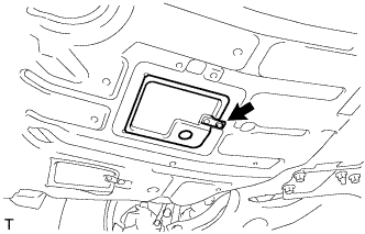
Close the oil pan drain service cover and install the clip.
 |
Add new oil.
- Standard oil capacity:
Item Specified Condition Drain and refill with oil filter change 5.9 liters ( 6.2 US qts, 5.2 Imp. qts) Drain and refill without oil filter change 5.5 liters ( 5.8 US qts, 4.8 Imp. qts) Dry fill 6.7 liters ( 7.1 US qts, 5.9 Imp. qts)
Install the oil filler cap.
| 90. ADD ENGINE COOLANT |
Tighten the radiator drain cock plug by hand.
Tighten the cylinder block drain cock plug.
- Момент затяжки:
- 12.7 Н*м{130 кгс*см, 10 фунт-сила-футов}
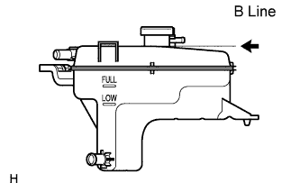
Add TOYOTA Super Long Life Coolant (SLLC) to the radiator reservoir filler opening.
Continue adding TOYOTA SLLC until it is filled to the B line.
- УКАЗАНИЕ:
- The B line is the lower edge of the inner wall of the filler neck.
- Standard capacity:
Item Specified Condition w/o Combustion Type Power Heater 7.3 liters
(7.7 US qts, 6.4 Imp. qts)w/ Combustion Type Power Heater 7.7 liters
(8.1 US qts, 6.8 Imp. qts)
- УКАЗАНИЕ:
- TOYOTA vehicles are filled with TOYOTA SLLC at the factory. In order to avoid damage to the engine cooling system and other technical problems, only use TOYOTA SLLC or similar high quality ethylene glycol based non-silicate, non-amine, non-nitrite, non-borate coolant with long-life hybrid organic acid technology (coolant with long-life hybrid organic acid technology consists of a combination of low phosphates and organic acids).
- ПРИМЕЧАНИЕ:
- Never use water as a substitute for engine coolant.
 |
Press the inlet and outlet radiator hoses several times by hand, and then check the level of the coolant.
If the coolant level drops below the B line, add TOYOTA SLLC to the B line.
Install the radiator reservoir cap.
Start the engine, and warm it up until the cooling fan operates.
Set the air conditioning as follows while warming up the engine.
Item Specified Condition Manual Air Conditioning System Fan speed - Any setting except "OFF" Temperature - Toward WARM
Air conditioning switch "OFF"Automatic Air Conditioning System Temperature - Toward MAX
Air conditioning switch "OFF"Maintain the engine speed at 2,000 to 2,500 rpm and warm up the engine until the cooling fan operates.
- ПРИМЕЧАНИЕ:
- Make sure that the radiator reservoir still has some coolant in it.
- Pay attention to the needle of the water temperature meter. Make sure that the needle does not show an abnormally high temperature.
- If there is not enough coolant, the engine may burn out or overheat.
- Immediately after starting the engine, if the radiator reservoir does not have any coolant, perform the following: 1) stop the engine, 2) wait until the coolant has cooled down, and 3) add coolant until the coolant is filled to the B line.
- Until the coolant level has stabilized, run the engine at 2,000 rpm.
Press the inlet and outlet radiator hoses several times by hand to bleed air.
- ПРЕДОСТЕРЕЖЕНИЕ:
- When pressing the radiator hoses:
- Wear protective gloves.
- Be careful as the radiator hoses are hot.
- Keep your hands away from the radiator fan.
Stop the engine and wait until the coolant cools down to ambient temperature.
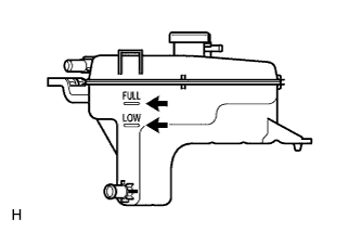
Check that the coolant level is between the FULL and LOW line.
If the coolant level is below the LOW line, repeat all of the procedures above.
If the coolant level is above the FULL line, drain coolant so that the coolant level is between the FULL and LOW line.
 |
| 91. BLEED AIR FROM FUEL SYSTEM |
Using the hand pump, bleed air from the fuel system until pumping becomes difficult.
 |
| 92. REGISTRATION OF INJECTOR COMPENSATION CODE |
Register injector compensation code (see page RAV4_ACA30 RM000000TJ4007X.html).
| 93. INSPECT ENGINE OIL LEAKS |
Start the engine. Make sure that no oil leaks from the connection point of the oil filter cap assembly.
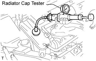
| 94. INSPECT ENGINE COOLANT LEAKS |
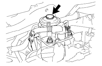
Remove the radiator reservoir cap.
- ПРЕДОСТЕРЕЖЕНИЕ:
- To avoid the danger of being burned, do not remove the radiator reservoir cap while the engine and radiator are still hot. Thermal expansion will cause hot engine coolant and steam to blow out from the radiator.
Fill the radiator with coolant, and then attach a radiator cap tester.
 |
Warm up the engine.
Pump the radiator cap tester to 137 kPa (1.4 kgf/cm2, 19 psi), and then check that the pressure does not drop.
If the pressure drops, check the hoses, radiator and water pump for leakage.
If there are no signs of external coolant leaks, check the heater core, cylinder block and head.
Reinstall the radiator cap.
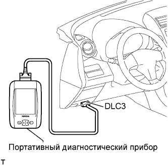
| 95. INSPECT FUEL LEAKS |
Perform the ACTIVE TEST.
Connect the intelligent tester to the DLC3.
Turn the ignition switch on (IG).
Turn the intelligent tester ON.
Enter the following menus: Powertrain / Engine / Active Test.
Perform the Active Test.
Intelligent Tester Display Test Details Control Range Diagnostic Notes Test the Fuel Leak Pressurizing common rail internal fuel pressure, and checking for fuel leaks Stop/Start - Fuel pressure inside common rail pressurized to specified value and engine speed increased to 2,000 rpm when Start is selected
- Above conditions to be maintained while test is Start
- Fuel pressure inside common rail pressurized to specified value and engine speed increased to 2,000 rpm when Start is selected
 |
| 96. INSPECT EXHAUST GAS LEAKS |
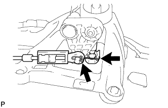
| 97. ADJUST TRANSMISSION CONTROL CABLE |
- УКАЗАНИЕ:
- After the shift lever or the shift cable is replaced, be sure to adjust the transmission control cable assembly.
- If the shift lever does not move (or the shift lever is difficult to move) to the 1st or 2nd position, or if it is possible to move the shift lever to the reverse position without pulling up the slider shaft, the length of the cable must be adjusted.
To release the lock (lock condition to lock release condition).
- УКАЗАНИЕ:
- While holding the shift lever in the reverse direction, lock the cable length adjustment mechanism of the select cable.
 |
Pressing the shift and select lever shaft (*1) and pin (*2), push in pin (*3) and check that the shift and select lever shaft is secured at the 1st-2nd gear selected position (the shaft comes to a stop at the position 8 mm (0.31 in.) below the N position).
Remove the stopper pin, release the lock, and reinsert the stopper pin.
 |
Turn the shift lever in the reverse direction without pulling up the slider shaft.
 |
While holding the shift lever in the reverse direction, lock the cable length adjustment mechanism of the select cable.
|
Release the pin that fixes the transmission outer lever.
Pull the pin toward the left front side of the vehicle.
 |
for new shift lever:
Remove the stopper pin and dispose of it.
 |
| 98. INSTALL FRONT FLOOR COVER |
Install the floor cover with the 3 clips, bolt and nut.
 |
| 99. INSTALL NO. 2 ENGINE UNDER COVER |
Install the under cover with the 2 clips.
| 100. INSTALL ENGINE UNDER COVER REAR LH |
Install the under cover with the 2 clips.
| 101. INSTALL ENGINE UNDER COVER REAR RH |
Install the under cover with the 2 clips.
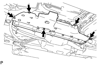
| 102. INSTALL NO. 1 ENGINE UNDER COVER |
Install the under cover with the 4 bolts and 12 clips.
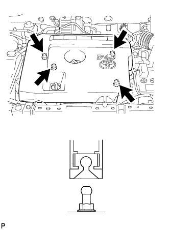
| 103. INSTALL NO. 1 ENGINE COVER |
Attach the 4 clips to install the engine cover.
 |
| 104. INSTALL RADIATOR SUPPORT OPENING COVER |
Установите 2 фиксатора.
 |
| 105. ADJUST FRONT WHEEL ALIGNMENT |
Adjust the front wheel alignment (see page RAV4_ACA30 RM00000227W000X.html).
| 106. INSPECT IDLE SPEED |
- ПРИМЕЧАНИЕ:
- When checking the idle speed, shift the transmission to the neutral position.
- УКАЗАНИЕ:
- For more information about the intelligent tester, refer to its operator's manual.
- If an intelligent tester is not available, use a tachometer's tester probe as a substitute.
Warm up and stop the engine.
Connect the intelligent tester to the DLC3.
 |
Turn the ignition switch on (IG).
Select the item:
Powertrain / Engine / Data List / Engine SPD.- УКАЗАНИЕ:
- Refer to the intelligent tester operator's manual if you need help to select Data List.
Inspect the engine idle speed.
- УКАЗАНИЕ:
- Turn all the electrical system and the A/C OFF.
- Inspect the engine idle speed with the cooling fan OFF.
- Standard idle speed:
- 750 to 850 rpm
Turn the ignition switch off.
Disconnect the intelligent tester from the DLC3.
| 107. INSPECT MAXIMUM ENGINE SPEED |
Start the engine.
Depress the accelerator pedal to the limit.
Check the maximum engine speed.
- Maximum engine speed:
- 5,100 to 5,250 rpm