Engine Unit (W/O Glow Plug Controller) Removal
REMOVE NO. 1 TIMING BELT COVER
REMOVE TIMING BELT
REMOVE NO. 1 TIMING BELT IDLER SUB-ASSEMBLY
REMOVE CRANKSHAFT PULLEY
REMOVE NO. 2 INTERCOOLER SUPPORT BRACKET
REMOVE INTERCOOLER SUPPORT BRACKET
REMOVE VENTILATION PIPE
REMOVE COMPRESSOR INLET ELBOW
REMOVE NO. 1 TURBO INSULATOR
REMOVE NO. 1 EXHAUST MANIFOLD HEAT INSULATOR
REMOVE NO. 1 TURBO WATER HOSE
REMOVE TURBINE OUTLET ELBOW
REMOVE TURBOCHARGER STAY
DISCONNECT TURBO OIL INLET PIPE SUB-ASSEMBLY
REMOVE EXHAUST MANIFOLD WITH TURBOCHARGER
REMOVE NO. 2 IDLE PULLEY ASSEMBLY
REMOVE GENERATOR ASSEMBLY
REMOVE GENERATOR BRACKET
REMOVE V-RIBBED BELT TENSIONER ASSEMBLY
REMOVE NO. 1 COMPRESSOR MOUNTING BRACKET (w/ Air Conditioning System)
REMOVE WATER INLET
REMOVE THERMOSTAT
REMOVE WATER OUTLET
REMOVE DIESEL THROTTLE BODY ASSEMBLY
REMOVE INTAKE MANIFOLD
REMOVE GLOW PLUG ASSEMBLY
REMOVE OIL FILTER SUB-ASSEMBLY
REMOVE FUEL INLET PIPE SUB-ASSEMBLY
REMOVE COMMON RAIL ASSEMBLY
REMOVE FUEL SUPPLY PUMP ASSEMBLY
REMOVE OIL COOLER COVER SUB-ASSEMBLY
REMOVE TIMING GEAR COVER INSULATOR (w/ EGR Cooler)
REMOVE VACUUM PUMP ASSEMBLY
REMOVE VANE PUMP ASSEMBLY
REMOVE CRANKSHAFT POSITION SENSOR
REMOVE CAMSHAFT POSITION SENSOR
REMOVE ENGINE COOLANT TEMPERATURE SENSOR
REMOVE FRONT NO. 1 ENGINE MOUNTING BRACKET RH
REMOVE FRONT NO. 1 ENGINE MOUNTING BRACKET LH
Engine Unit (W/O Glow Plug Controller) -- Removal |
- NOTICE:
- When replacing the injectors (including shuffling the injectors between the cylinders), common rail or cylinder head, it is necessary to replace the injection pipes with new ones.
- When replacing the fuel supply pump, common rail, cylinder block, cylinder head, cylinder head gasket or timing gear case, it is necessary to replace the fuel inlet pipe with a new one.
- After removing the injection pipes, clean them with a brush and compressed air.
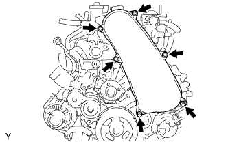
| 1. REMOVE NO. 1 TIMING BELT COVER |
Remove the 6 bolts, 6 washers and timing belt cover.
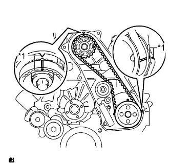
Turn the crankshaft clockwise and align the timing marks as shown in the illustration.
Text in Illustration*1
| Timing Mark
|
- HINT:
- If reusing the timing belt, place matchmarks on the timing belt so that it can be installed exactly as before.
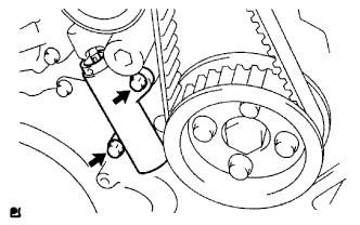
Uniformly loosen and remove the 2 bolts and No. 1 timing belt tensioner.
Remove the timing belt.
- HINT:
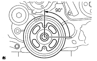
- If turning the camshaft while the timing belt is removed, turn the crankshaft 90° counterclockwise as shown in the illustration.
- When installing the timing belt, turn the camshaft to align the timing marks, and then turn the crankshaft clockwise to align the timing marks.
| 3. REMOVE NO. 1 TIMING BELT IDLER SUB-ASSEMBLY |
- NOTICE:
- When inspecting the No. 1 timing belt idler, do not remove it unless absolutely necessary.
Using a 10 mm hexagon wrench, remove the bolt, No. 1 timing belt idler and washer.
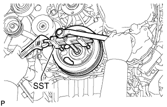
| 4. REMOVE CRANKSHAFT PULLEY |
Using SST, hold the crankshaft pulley and loosen the pulley bolt.
- SST
- 09213-58014
09330-00021
Using SST, remove the pulley bolt and crankshaft pulley.
- SST
- 09950-50013(09951-05010,09952-05010,09953-05020,09954-05021)
| 5. REMOVE NO. 2 INTERCOOLER SUPPORT BRACKET |
Remove the 2 bolts and No. 2 intercooler support bracket.
| 6. REMOVE INTERCOOLER SUPPORT BRACKET |
Remove the 2 bolts and intercooler support bracket.
| 7. REMOVE VENTILATION PIPE |
Remove the bolt and disconnect the 2 ventilation hoses and ventilation pipe.
| 8. REMOVE COMPRESSOR INLET ELBOW |
Disconnect the 2 connectors from the turbocharger.
Detach the wire harness clamp.
Remove the 2 nuts, compressor inlet elbow and gasket.
| 9. REMOVE NO. 1 TURBO INSULATOR |
Remove the 2 bolts and No. 1 turbo insulator.
| 10. REMOVE NO. 1 EXHAUST MANIFOLD HEAT INSULATOR |
Remove the bolt and No. 1 exhaust manifold heat insulator.
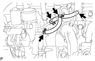
| 11. REMOVE NO. 1 TURBO WATER HOSE |
Remove the 2 No. 1 turbo water hoses.
| 12. REMOVE TURBINE OUTLET ELBOW |
Remove the 3 nuts, turbine outlet elbow and gasket.
| 13. REMOVE TURBOCHARGER STAY |
Remove the 2 bolts, nut and turbocharger stay.
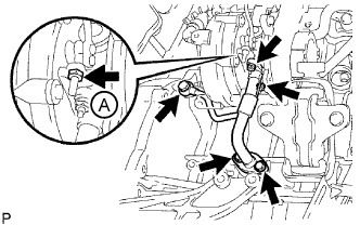
| 14. DISCONNECT TURBO OIL INLET PIPE SUB-ASSEMBLY |
Remove the 2 bolts, 2 nuts, union bolt, turbo oil inlet pipe and 3 gaskets.
- NOTICE:
- Do not loosen the nut labeled A.
| 15. REMOVE EXHAUST MANIFOLD WITH TURBOCHARGER |
Remove the 8 nuts, 8 plate washers, 8 collars and exhaust manifold with turbocharger shown in the illustration.
| 16. REMOVE NO. 2 IDLE PULLEY ASSEMBLY |
Remove the bolt, pulley plate, No. 2 idle pulley and spacer.
| 17. REMOVE GENERATOR ASSEMBLY |
Remove the nut and generator wire.
Disconnect the generator connector.
Remove the 2 bolts and generator.
| 18. REMOVE GENERATOR BRACKET |
Remove the bolt and generator bracket.
| 19. REMOVE V-RIBBED BELT TENSIONER ASSEMBLY |
Remove the 4 bolts and V-ribbed belt tensioner.
| 20. REMOVE NO. 1 COMPRESSOR MOUNTING BRACKET (w/ Air Conditioning System) |
Remove the 4 bolts and No. 1 compressor mounting bracket.
Disconnect the wire harness clamp.
Remove the 3 bolts and water inlet.
Remove the bolt and wire harness clamp bracket from the water inlet.
Remove the thermostat from the cylinder block.
Remove the gasket from the thermostat.
Remove the 2 bolts, water outlet and gasket.
| 24. REMOVE DIESEL THROTTLE BODY ASSEMBLY |
Disconnect the 2 connectors.
Remove the 2 bolts, 2 nuts, diesel throttle body and gasket.
| 25. REMOVE INTAKE MANIFOLD |
(HILUX_TGN26 RM00000143Y01YX.html)
| 26. REMOVE GLOW PLUG ASSEMBLY |
(HILUX_TGN26 RM0000013XP01BX.html)
| 27. REMOVE OIL FILTER SUB-ASSEMBLY |
Using SST, remove the oil filter.
- SST
- 09228-07501
- HINT:
- Insert the drain hose in the oil filter. Put the disposal container beneath the drain hose to collect the oil from the oil filter.
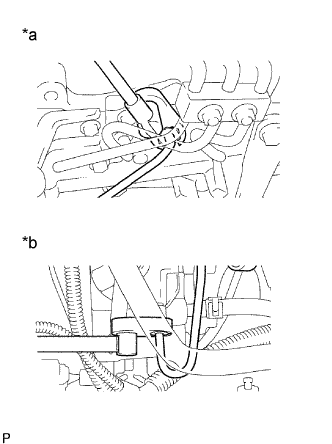
| 28. REMOVE FUEL INLET PIPE SUB-ASSEMBLY |
Using a 17 mm union nut wrench, loosen the union nuts and remove the fuel inlet pipe.
Text in Illustration*a
| Common Rail Side
|
*b
| Fuel Supply Pump Side
|
| 29. REMOVE COMMON RAIL ASSEMBLY |
- NOTICE:
- Do not remove the pressure discharge valve or fuel pressure sensor.
Disconnect the 2 connectors.
Remove the 2 bolts, common rail and No. 2 intake manifold insulator.
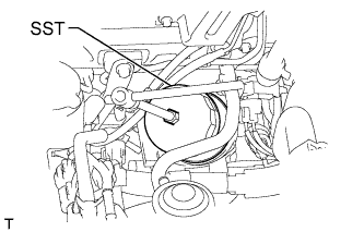
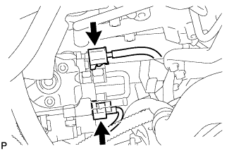
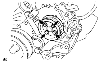
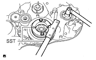
| 30. REMOVE FUEL SUPPLY PUMP ASSEMBLY |
Disconnect the 2 fuel hoses.
Disconnect the fuel temperature sensor connector and suction control valve connector.
Remove the 4 bolts indicated by the arrows in the illustration.
Remove the No. 2 camshaft timing pulley flange and pump drive shaft pulley.
Remove the set nut and O-ring while holding the crankshaft pulley using SST.
- SST
- 09213-58014
09330-00021
Loosen the 2 nuts.
Using SST, disconnect the fuel supply pump from the injection gear.
- SST
- 09950-50013(09951-05010,09952-05010,09953-05020,09954-05021)
- NOTICE:
- Apply lubricant to the threads and tip of SST (center bolt) before using it.
Remove the 2 nuts and fuel supply pump.
- NOTICE:
- Do not hold or carry the fuel supply pump by the pipe.
- The fuel supply pump must be kept horizontal.
Remove the O-ring.
| 31. REMOVE OIL COOLER COVER SUB-ASSEMBLY |
Disconnect the oil pressure switch connector.
Remove the 2 nuts and disconnect the No. 2 vacuum transmitting pipe from the oil cooler cover.
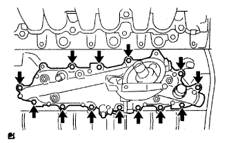
Remove the 13 bolts, oil cooler cover and gasket.
| 32. REMOVE TIMING GEAR COVER INSULATOR (w/ EGR Cooler) |
Remove the bolt and timing gear cover insulator.
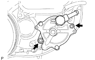
| 33. REMOVE VACUUM PUMP ASSEMBLY |
Remove the 2 nuts, vacuum pump and 2 O-rings.
| 34. REMOVE VANE PUMP ASSEMBLY |
Remove the 2 nuts, vane pump and O-ring.
| 35. REMOVE CRANKSHAFT POSITION SENSOR |
Disconnect the crankshaft position sensor connector.
Detach the 4 clips, and remove the bolt and crankshaft position sensor.
| 36. REMOVE CAMSHAFT POSITION SENSOR |
Disconnect the camshaft position sensor connector.
Remove the bolt and camshaft position sensor.
| 37. REMOVE ENGINE COOLANT TEMPERATURE SENSOR |
Disconnect the engine coolant temperature sensor connector.
Remove the engine coolant temperature sensor.
Remove the gasket from the engine coolant temperature sensor.
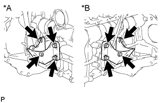
| 38. REMOVE FRONT NO. 1 ENGINE MOUNTING BRACKET RH |
Remove the 4 bolts and front No. 1 engine mounting bracket.
Text in Illustration*A
| RH Side
|
*B
| LH Side
|
| 39. REMOVE FRONT NO. 1 ENGINE MOUNTING BRACKET LH |
Remove the 4 bolts and front No. 1 engine mounting bracket.