INSTALL PUMP IMPELLER DRIVE PLATE (for Automatic Transmission)
INSPECT AND ADJUST CLUTCH COVER ASSEMBLY (for Manual Transmission)
INSTALL AUTOMATIC TRANSMISSION ASSEMBLY (for Automatic Transmission)
INSTALL DRIVE PLATE AND TORQUE CONVERTER SETTING BOLT (for Automatic Transmission)
INSTALL MANUAL TRANSMISSION ASSEMBLY (for Manual Transmission)
CONNECT COOLER COMPRESSOR ASSEMBLY (w/ Air Conditioning System)
Engine Assembly (W/O Glow Plug Controller) -- Installation |
- NOTICE:
- When replacing the injectors (including shuffling the injectors between the cylinders), common rail or cylinder head, it is necessary to replace the injection pipes with new ones.
- When replacing the fuel supply pump, common rail, cylinder block, cylinder head, cylinder head gasket or timing gear case, it is necessary to replace the fuel inlet pipe with a new one.
- After removing the injection pipes, clean them with a brush and compressed air.
| 1. INSTALL FRONT ENGINE MOUNTING INSULATOR |
Install the 2 front engine mounting insulators with the 2 nuts.
- Torque:
- 48 N*m{489 kgf*cm, 35 ft.*lbf}
| 2. INSTALL ENGINE WIRE |
Install the engine wire to the engine.
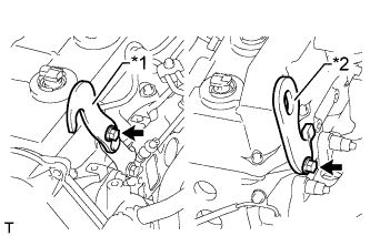
| 3. INSTALL ENGINE HANGERS |
Install a No. 1 engine hanger and No. 2 engine hanger with 2 bolts as shown in the illustration.
- Torque:
- for No. 1 engine hanger:
- 25 N*m{255 kgf*cm, 18 ft.*lbf}
- for No. 2 engine hanger:
- 60 N*m{612 kgf*cm, 44 ft.*lbf}
Text in Illustration *1 No. 1 Engine Hanger *2 No. 2 Engine Hanger - NOTICE:
- Install the engine hangers with new bolts.
- HINT:
- Part No.
No. 1 Engine Hanger 12284-30020 No. 2 Engine Hanger 12282-67030 Bolt 91552-81014 and 91642-81030
 |
| 4. REMOVE ENGINE FROM ENGINE STAND |
Attach an engine sling device and hang the engine with a chain block.
Remove the engine from the engine stand.
| 5. INSTALL ENGINE ASSEMBLY |
Slowly lower the engine into the engine compartment.
Install the engine with the 4 bolts and 4 nuts.
- Torque:
- 38 N*m{387 kgf*cm, 28 ft.*lbf}
Remove the 2 bolts and 2 engine hangers.
| 6. INSTALL REAR END PLATE |
Install the rear end plate with the bolt.
- Torque:
- 8.0 N*m{82 kgf*cm, 71 in.*lbf}
| 7. INSTALL PUMP IMPELLER DRIVE PLATE (for Automatic Transmission) |
Clean the bolts and their holes.
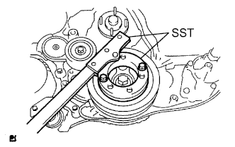
Using SST, hold the crankshaft pulley.
- SST
- 09213-58014
09330-00021
 |
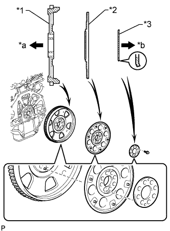
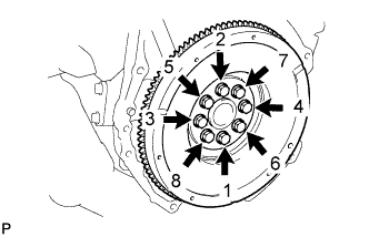
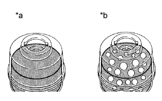
Install the flywheel and ring gear, the pump impeller drive plate and the rear drive plate spacer to the crankshaft.
Text in Illustration *1 Flywheel and Ring Gear *2 Pump Impeller Drive Plate *3 Rear Drive Plate Spacer *a Engine Side *b Transmission Side - NOTICE:
- Align either hole in the pump impeller drive plate and either hole in the rear drive plate spacer with the knock pin of the flywheel and ring gear, and then install the flywheel and ring gear, the pump impeller drive plate and the rear drive plate spacer to the crankshaft.
- HINT:
- As the rear drive plate spacer and pump impeller drive plate are not reversible, be sure to install them in the direction shown in the illustration.
 |
Install and uniformly tighten and tighten the 8 bolts in several steps in the sequence shown in the illustration.
- Torque:
- 178 N*m{1815 kgf*cm, 131 ft.*lbf}
- NOTICE:
- Do not start the engine for at least an hour after installing the flywheel and ring gear.
 |
| 8. INSTALL FLYWHEEL SUB-ASSEMBLY (for Manual Transmission) |
Clean the bolts and their holes.
Apply adhesive to 2 or 3 threads at the end of each bolt.
- Adhesive:
- Toyota Genuine Adhesive 1324, Three Bond 1324 or equivalent
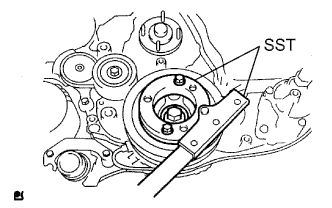
Using SST, hold the crankshaft pulley.
- SST
- 09213-58014
09330-00021
 |
Install the flywheel to the crankshaft.
Install and uniformly tighten the 8 bolts in the sequence shown in the illustration.
- Torque:
- 178 N*m{1815 kgf*cm, 131 ft.*lbf}
- NOTICE:
- Do not start the engine for at least 1 hour after installation.
 |
| 9. INSTALL CLUTCH DISC ASSEMBLY (for Manual Transmission) |
Insert SST into the clutch disc. Then insert SST (together with the clutch disc) into the flywheel.
- SST
- 09301-00110
- NOTICE:
- Be sure to install the clutch disc so that it is facing in the correct direction.
 |
| 10. INSTALL CLUTCH COVER ASSEMBLY (for Manual Transmission) |
Align the matchmarks on the clutch cover and flywheel.
Text in Illustration *1 Matchmark
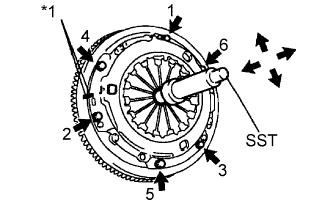 |
Tighten the 6 bolts as described below.
Determine the first bolt to be tightened by choosing the bolt closest to the knock pin.
Uniformly tighten the 6 bolts in diametrically opposite pairs relative to the position of the first bolt. Use the illustration as a reference.
Lightly move SST up and down, and right and left.
- SST
- 09301-00110
Check that the disc is in the center, and then tighten the bolts.
- Torque:
- 19 N*m{195 kgf*cm, 14 ft.*lbf}
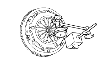
| 11. INSPECT AND ADJUST CLUTCH COVER ASSEMBLY (for Manual Transmission) |
Using a dial indicator with a roller instrument, measure the diaphragm spring tip alignment.
- Maximum misalignment:
- 0.5 mm (0.020 in.)
If the misalignment is more than the maximum, use SST to adjust the diaphragm spring tip alignment.
- SST
- 09333-00013
 |
| 12. INSTALL REAR NO. 1 ENGINE MOUNTING INSULATOR |
- HINT:
- Perform this procedure only when replacement of the rear No. 1 engine mounting insulator is necessary.
Install the rear No. 1 engine mounting insulator with the 4 bolts.
- Torque:
- 47 N*m{479 kgf*cm, 35 ft.*lbf}
| 13. INSTALL AUTOMATIC TRANSMISSION ASSEMBLY (for Automatic Transmission) |
- for A340F: (HILUX_TGN26 RM0000010NT02WX.html)
- for A750F: (HILUX_TGN26 RM0000013F401HX.html)
| 14. INSTALL DRIVE PLATE AND TORQUE CONVERTER SETTING BOLT (for Automatic Transmission) |
| 15. INSTALL MANUAL TRANSMISSION ASSEMBLY (for Manual Transmission) |
- for 2WD: (HILUX_TGN26 RM0000011B0019X.html)
- for 4WD: (HILUX_TGN26 RM0000011AJ00YX.html)
| 16. CONNECT COOLER COMPRESSOR ASSEMBLY (w/ Air Conditioning System) |
Connect the cooler compressor with the 4 bolts.
- Torque:
- 25 N*m{250 kgf*cm, 18 ft.*lbf}
| 17. CONNECT WIRE HARNESS |
Connect the 4 ECM connectors.
for Automatic Transmission:
Connect the 3 TCM connectors.
Connect the turbo motor driver connector.
for 4WD:
Connect the 4WD control ECU connector.
Connect the 3 injector driver connectors.
Attach the clamp and connect the wire harness with the 2 nuts.
- Torque:
- 13 N*m{131 kgf*cm, 9 ft.*lbf}
Connect the ground cable with the bolt.
- Torque:
- 30 N*m{306 kgf*cm, 22 ft.*lbf}
Connect the 2 engine room junction block connectors.
Connect the engine room junction block wire with the nut.
- Torque:
- 13 N*m{133 kgf*cm, 10 ft.*lbf}
Install the side engine room relay block cover.
Install the upper relay block cover.
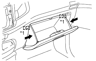
| 18. INSTALL GLOVE COMPARTMENT DOOR ASSEMBLY |
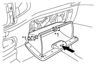 |
Attach the 2 hinges to install the glove compartment door.
Text in Illustration *1 Hinge
While pushing in the sides of the glove compartment door as indicated by the arrows in the illustration, close the door to engage it to the 2 stoppers.
Text in Illustration *1 Stopper
 |
| 19. CONNECT UNION TO CONNECTOR TUBE HOSE |
Connect the union to connector tube hose.
| 20. CONNECT FUEL HOSE |
Connect the 2 fuel hoses.
| 21. CONNECT PRESSURE FEED TUBE ASSEMBLY |
Connect the pressure feed tube.
- Torque:
- 44 N*m{449 kgf*cm, 32 ft.*lbf}
- NOTICE:
- Use the formula to calculate special torque values for situations where a union nut wrench is combined with a torque wrench (HILUX_TGN26 RM000004QR1006X.html).
Connect the oil reservoir to pump hose.
| 22. CONNECT HEATER HOSE |
Connect the 2 heater hoses.
| 23. INSTALL PROPELLER WITH CENTER BEARING SHAFT ASSEMBLY |
| 24. INSTALL FRONT PROPELLER SHAFT ASSEMBLY (for 4WD) |
Completely remove any oil or the like and clean the contact surfaces of the propeller shaft flange and transfer flange.
Align the matchmarks on the propeller shaft flange and transfer flange.
Install the propeller shaft with the 4 nuts and 4 washers.
- Torque:
- 88 N*m{899 kgf*cm, 65 ft.*lbf}
Completely remove any oil or the like and clean the contact surfaces of the propeller shaft flange and differential flange.
Align the matchmarks on the propeller shaft flange and differential flange.
Connect the propeller shaft with the 4 bolts, 4 nuts and 4 washers.
- Torque:
- 88 N*m{899 kgf*cm, 65 ft.*lbf}
| 25. INSTALL FRONT EXHAUST PIPE ASSEMBLY |
| 26. INSTALL STARTER ASSEMBLY |
| 27. INSTALL RADIATOR ASSEMBLY |
| 28. INSTALL INTERCOOLER ASSEMBLY WITH INTAKE AIR CONNECTOR |
| 29. INSTALL AIR CLEANER ASSEMBLY |
Connect the air cleaner hose.
Install the cleaner with the 2 bolts.
- Torque:
- 14 N*m{143 kgf*cm, 10 ft.*lbf}
Tighten the hose clamp.
Connect the connector to the mass air flow meter connector.
| 30. INSTALL BATTERY TRAY |
| 31. INSTALL BATTERY |
| 32. INSTALL BATTERY CLAMP SUB-ASSEMBLY |
Install the battery clamp with the bolt and nut.
- Torque:
- 5.4 N*m{55 kgf*cm, 48 in.*lbf}
| 33. ADD POWER STEERING FLUID |
| 34. ADD TRANSMISSION FLUID (for Automatic Transmission) |
- Fluid type:
- Toyota Genuine ATF TYPE T-IV
| 35. ADD TRANSMISSION OIL (for Manual Transmission) |
Add manual transmission oil until the oil level is within 5 mm (0.196 in.) from the bottom of the filler plug opening.
Text in Illustration *a 0 to 5 mm (0 to 0.196 in.) - Oil grade:
- GL-4 or GL-5
- Viscosity:
- SAE 75W-90, 80 or 80W-90
- Standard capacity:
- 2.2 liters (2.3 US qts, 1.9 Imp. qts)
 |
Install a new gasket and the filler plug.
- Torque:
- 37 N*m{377 kgf*cm, 27 ft.*lbf}
| 36. ADD ENGINE OIL |
Add new engine oil.
- Standard Oil Grade:
Item Oil Grade Oil Viscosity (SAE) w/o Glow Plug Controller G-DLD1, API CF-4, CF or ACEA B1 - 5W-30
- 10W-30
- 15W-40
- 20W-50w/ Glow Plug Controller for i-ART API CF-4, CF or ACEA B1 - 5W-30
- 10W-30
- 15W-40
- 20W-50
(5W-30 is best choice for fuel economy and good starting in cold winter.)for DPF ACEA C2 - 0W-30
- 5W-30
- Standard Capacity:
Item Specified Condition Drain and refill without oil filter change 6.6 liters (7.0 US qts, 5.8 Imp. qts) Drain and refill with oil filter change 6.9 liters (7.3 US qts, 6.1 Imp. qts) Dry fill 7.4 liters (7.8 US qts, 6.5 Imp. qts)
Install the oil filler cap.
| 37. INSTALL HOOD SUB-ASSEMBLY |
Install the hood with the 4 bolts.
- Torque:
- 13 N*m{133 kgf*cm, 10 ft.*lbf}
Connect the washer nozzle hose.
Adjust the hood (HILUX_TGN26 RM00000138K01ZX.html).
| 38. CONNECT CABLE TO NEGATIVE BATTERY TERMINAL |
- NOTICE:
- When disconnecting the cable, some systems need to be initialized after the cable is reconnected (HILUX_TGN26 RM000004QR300CX.html).
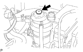
| 39. BLEED AIR FROM FUEL SYSTEM |
Using the hand pump mounted on the fuel filter cap, bleed the air from the fuel system. Continue pumping until the pump resistance increases.
- NOTICE:
- Hand pump pumping speed: Max. 2 strokes/ sec.
- The hand pump must be pushed with a full stroke during pumping.
- When the fuel pressure at the supply pump inlet port reaches a saturated pressure, the hand pump resistance increases.
- If pumping is interrupted during the air bleeding process, fuel in the fuel line may return to the fuel tank. Continue pumping until the hand pump resistance increases.
- If the hand pump resistance does not increase despite consecutively pumping 200 times or more, there may be a fuel leak between the fuel tank and fuel filter, the hand pump may be malfunctioning, or the vehicle may have run out of fuel.
- If air bleeding using the hand pump is incomplete, the common rail pressure does not rise to the pressure range necessary for normal use, and the engine cannot be started.
 |
Check if the engine starts.
- NOTICE:
- Even if air bleeding using the hand pump has been completed, the starter may need to be cranked for 10 seconds or more to start the engine.
- Do not crank the engine continuously for more than 20 seconds. The battery may be discharged.
- Use a fully-charged battery.
When the engine can be started, proceed to the next step.
If the engine cannot be started, bleed the air again using the hand pump until the hand pump resistance increases (refer to the procedures above). Then start the engine.
Turn the ignition switch off.
Connect the intelligent tester to the DLC3.
Turn the ignition switch to ON and turn the intelligent tester on.
Clear the DTCs.
- w/ EGR Cooler: (HILUX_TGN26 RM000000PDK0SYX.html)
- w/o EGR Cooler: (HILUX_TGN26 RM000000PDK0T9X.html)
- w/ EGR Cooler: (HILUX_TGN26 RM000000PDK0SYX.html)
Start the engine.*1
Enter the following menus: Powertrain / Engine and ECT / Active Test / Test the Fuel Leak.*2
Text in Illustration *a Reference
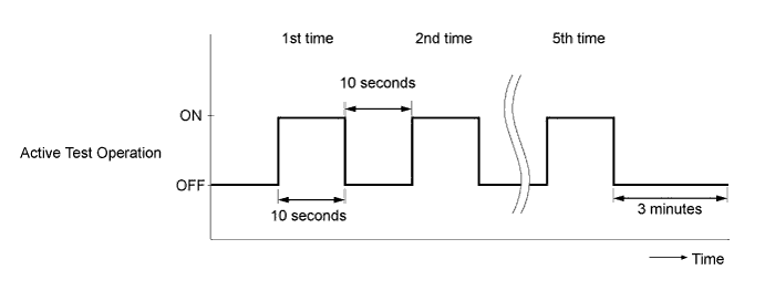
(Active Test Operation)
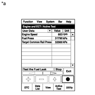 |
Perform the following test 5 times with on/off intervals of 10 seconds: Active Test / Test the Fuel Leak.*3
Allow the engine to idle for 3 minutes or more after performing the Active Test for the fifth time.
- HINT:
- When the Active Test "Test the Fuel Leak" is used to change the pump control mode, the actual fuel pressure inside the common rail drops below the target fuel pressure when the Active Test is off, but this is normal and does not indicate a pump malfunction.
Enter the following menus: Powertrain / Engine and ECT / DTC.
Read Current DTCs.
Clear the DTCs.
- w/ EGR Cooler: (HILUX_TGN26 RM000000PDK0SYX.html)
- w/o EGR Cooler: (HILUX_TGN26 RM000000PDK0T9X.html)
- HINT:
- It is necessary to clear the DTCs, as DTC P1604 or P1605 may be stored when air is bled from the fuel system after replacing or repairing fuel system parts.
- w/ EGR Cooler: (HILUX_TGN26 RM000000PDK0SYX.html)
Repeat steps *1 to *3.
Enter the following menus: Powertrain / Engine and ECT / DTC.
Read Current DTCs.
- OK:
- No DTCs are output.
| 40. ADD ENGINE COOLANT |
Tighten the radiator drain cock plug by hand.
Tighten the cylinder block drain cock plug.
- Torque:
- 8.0 N*m{82 kgf*cm, 71 in.*lbf}
Fill the radiator with TOYOTA Super Long Life Coolant (SLLC) to the B line of the radiator reservoir.
- Standard Capacity:
Item Specified Condition for Automatic Transmission 11.1 liters (11.7 US qts, 9.8 Imp. qts) for Manual Transmission 9.8 liters (10.4 US qts, 8.6 Imp. qts)
- NOTICE:
- Never use water as a substitute for engine coolant.
- HINT:
- TOYOTA vehicles are filled with TOYOTA SLLC at the factory. In order to avoid damage to the engine cooling system and other technical problems, only use TOYOTA SLLC or similar high quality ethylene glycol based non-silicate, non-amine, non-nitrite, non-borate coolant with long-life hybrid organic acid technology (coolant with long-life hybrid organic acid technology consists of a combination of low phosphates and organic acids).
- Please contact your TOYOTA dealer for further details.
Press the inlet and outlet radiator hoses several times by hand, and then check the level of the coolant.
If the coolant level drops below the B line, add TOYOTA SLLC to the B line.
Install the radiator reservoir cap.
Using a wrench, install the vent plug.
- Torque:
- 2.0 N*m{20 kgf*cm, 17 in.*lbf}
Bleed air from the cooling system.
Warm up the engine until the thermostat opens. While the thermostat is open, circulate the coolant for several minutes.
Maintain the engine speed at 2500 to 3000 rpm.
Press the inlet and outlet radiator hoses several times by hand to bleed air.
- CAUTION:
- When pressing the radiator hoses:
- Wear protective gloves.
- Be careful as the radiator hoses are hot.
- Keep your hands away from the radiator fan.
Stop the engine and wait until the coolant cools down to ambient temperature.
- CAUTION:
- Do not remove the radiator reservoir cap while the engine and radiator are still hot. Pressurized, hot engine coolant and steam may be released and cause serious burns.
After the coolant cools down, check that the coolant level is at the F line.
If the coolant level is below the F line, add TOYOTA SLLC to the F line.
| 41. BLEED AIR FROM POWER STEERING SYSTEM |
Check the fluid level.
Jack up the front of the vehicle and support it with stands.
Turn the steering wheel.
With the engine stopped, turn the steering wheel slowly from lock to lock several times.
Lower the vehicle.
Start the engine. Run the engine at idle for a few minutes.
Turn the steering wheel.
With the engine idling, turn the steering wheel to the left or right full lock position and hold it there for 2 to 3 seconds. Then turn the steering wheel to the opposite full lock position and hold it there for 2 to 3 seconds.
Repeat the step above several times.
Stop the engine.
Check for foaming or emulsification. If the system has to be bled twice because of foaming or emulsification, check for fluid leaks in the system.
Text in Illustration *a Correct *b Incorrect
 |
Check the fluid level.
| 42. INSPECT POWER STEERING FLUID LEVEL |
Keep the vehicle level.
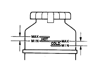 |
With the engine stopped, check the power steering fluid level in the oil reservoir. If necessary, add power steering fluid.
- Power steering fluid (for TMT made):
- "TEXAMATIC 1888" or equivalent
- (for TASA, TDV made):
- ATF "DEXRON 3" or equivalent
- (for TSAM made):
- "TEXAMATIC 1322S" or equivalent
- HINT:
- If the fluid is hot, check that the fluid level is within the HOT range on the oil reservoir. If the fluid is cold, check that the fluid level is within the COLD range.
Start the engine and run it at idle.
Turn the steering wheel to the left or right full lock position, and then turn the steering wheel to the opposite full lock position. Repeat this several times to raise fluid temperature.
- Standard fluid temperature:
- 75 to 80°C (167 to 176°F)
Check for foaming or emulsification. If foaming or emulsification is identified, bleed air from the power steering system.
Text in Illustration *a Correct *b Incorrect
|
With the engine idling, measure the fluid level in the oil reservoir.
Text in Illustration *a Engine idling *b Engine stopped *c 5 mm or Less
 |
Stop the engine.
Wait a few minutes and remeasure the fluid level in the oil reservoir.
- Maximum fluid level increase:
- 5 mm (0.197 in.)
Check the fluid level.
| 43. PERFORM REGISTRATION |
Perform registration of the injector compensation codes.
- w/ EGR Cooler: (HILUX_TGN26 RM0000012XK07FX_02_0003.html)
- w/o EGR Cooler: (HILUX_TGN26 RM0000012XK07GX_02_0003.html)
- w/ EGR Cooler: (HILUX_TGN26 RM0000012XK07FX_02_0003.html)
Perform pilot quantity learning.
- w/ EGR Cooler: (HILUX_TGN26 RM0000012XK07FX_02_0009.html)
- w/o EGR Cooler: (HILUX_TGN26 RM0000012XK07GX_02_0009.html)
- w/ EGR Cooler: (HILUX_TGN26 RM0000012XK07FX_02_0009.html)
| 44. INSPECT FOR COOLANT LEAK |
- CAUTION:
- Do not remove the radiator reservoir cap while the engine and radiator are still hot. Pressurized, hot engine coolant and steam may be released and cause serious burns.
- NOTICE:
- Before each inspection, turn the A/C switch off.
Fill the radiator with coolant and attach a radiator cap tester.
Warm up the engine.
Using the radiator cap tester, increase the pressure inside the radiator to 118 kPa (1.2 kgf/cm2, 17 psi), and check that the pressure does not drop.
If the pressure drops, check the hoses, radiator and water pump for leaks. If no external leaks are found, check the heater core, cylinder block and head.
| 45. INSPECT FOR OIL LEAK |
Start the engine. Make sure that there are no oil leaks from the areas that were worked on.
| 46. INSPECT FOR EXHAUST GAS LEAK |
| 47. INSPECT FOR FUEL LEAK |
- CAUTION:
- During Active Test mode, the engine speed becomes high and the combustion noise becomes loud, so pay attention.
- During Active Test mode, the fuel pressure becomes high. Be extremely careful not to expose your eyes, hands, or body to escaping fuel.
Check that there are no leaks from any part of the fuel system when the engine is stopped. If there is fuel leakage, repair or replace parts as necessary.
Start the engine and check that there are no leaks from any part of the fuel system. If there is fuel leakage, repair or replace parts as necessary.
Disconnect the return hose from the common rail.
Start the engine and check for fuel leaks from the return pipe.
If there is fuel leakage, replace the common rail.
Connect the intelligent tester to the DLC3.
Start the engine and push the intelligent tester main switch on.
Select the Fuel Leak test from the Active Test mode on the intelligent tester.
If the intelligent tester is not available, fully depress the accelerator pedal quickly. Increase the engine speed to the maximum and maintain that speed for 2 seconds. Repeat this operation several times.
Check that there are no leaks from any part of the fuel system.
- NOTICE:
- A return pipe leakage of less than 10 cc (0.6 cu in.) per minute is acceptable.
Reconnect the return hose to the common rail.
| 48. CHECK ENGINE IDLE SPEED AND MAXIMUM SPEED |
- HINT:
- For more information about the intelligent tester, refer to its operator's manual.
- If a intelligent tester is not available, use a tachometer's tester probe as a substitute.
Connect the intelligent tester to the DLC3.
If a tester is not available, connect the tester probe of a tachometer to terminal 9 (TAC) of the DLC3 with SST.
- SST
- 09843-18040
Text in Illustration *a Front view of DLC3
 |
Inspect the idle speed.
- HINT:
- Make sure that the engine is warmed up.
- Make sure that the A/C switch is off.
Start the engine and measure the idle speed.
- Standard idle speed:
- 700 to 800 rpm
Inspect the maximum speed.
Start the engine.
Fully depress the accelerator pedal.
Measure the maximum speed.
- Maximum Speed:
- 4450 to 4750 rpm
If the tester probe of a tachometer is connected to the DLC3, disconnect the tester probe together with SST from terminal 9 of the DLC3.
Disconnect the intelligent tester from the DLC3.
| 49. INSPECT ENGINE OIL LEVEL |
Warm up the engine, stop the engine and wait 5 minutes. The engine oil level should be between the dipstick low level mark and full level mark.
If low, check for leakage and add oil up to the full level mark.- NOTICE:
- Do not fill engine oil above the full level mark.
| 50. INSTALL NO. 2 ENGINE UNDER COVER |
- Torque:
- 28 N*m{286 kgf*cm, 21 ft.*lbf}
| 51. INSTALL NO. 1 ENGINE UNDER COVER |
- Torque:
- 28 N*m{286 kgf*cm, 21 ft.*lbf}