DESCRIPTION
MONITOR STRATEGY
TYPICAL MALFUNCTION THRESHOLDS
CONFIRMATION DRIVING PATTERN
WIRING DIAGRAM
INSPECTION PROCEDURE
CHECK HARNESS AND CONNECTOR (ECM - BATTERY)
INSPECT BATTERY
CHECK BATTERY TERMINAL
CHECK WHETHER DTC OUTPUT RECURS
DESCRIPTION
The battery supplies electricity to the ECM even when the ignition switch is off. This power allows the ECM to store data such as DTC history, freeze frame data and fuel trim values. If the battery voltage falls below a minimum level, the memory is cleared and the ECM determines that there is a malfunction in the power supply circuit. When the engine is next started, the ECM illuminates the MIL and stores the DTC.DTC No.
| DTC Detection Condition
| Trouble Area
|
P0560
| Open in the ECM backup power source circuit (1 trip detection logic).
| - Open in backup power source circuit
- Battery
- Battery terminals
- EFI fuse
- ECM
|
- HINT:
- If DTC P0560 is stored, the ECM does not store other DTCs and the data stored in the ECM is partly cleared.
MONITOR STRATEGY
Required Sensors/Components
| ECM
|
Frequency of Operation
| Continuous
|
TYPICAL MALFUNCTION THRESHOLDS
Stand-by RAM
| Initialized
|
ECM power source
| Below 3.5 V
|
CONFIRMATION DRIVING PATTERN
- Turn the ignition switch to ON and wait for 5 seconds or more.
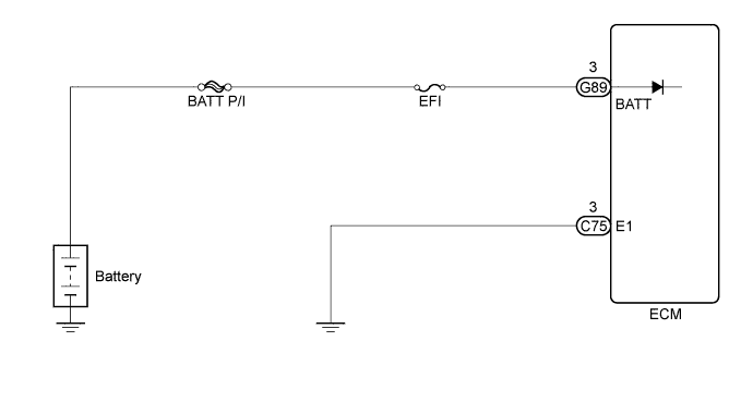
WIRING DIAGRAM
INSPECTION PROCEDURE
- NOTICE:
- Inspect the fuses for circuits related to this system before performing the following inspection procedure.
- HINT:
- Read freeze frame data using the intelligent tester. Freeze frame data records the engine condition when malfunctions are detected. When troubleshooting, freeze frame data can help determine if the vehicle was moving or stationary, if the engine was warmed up or not, if the air-fuel ratio was lean or rich, and other data from the time the malfunction occurred.
| 1.CHECK HARNESS AND CONNECTOR (ECM - BATTERY) |
Disconnect the ECM connector.
Disconnect the cable from the positive (+) battery terminal.
Measure the resistance according to the value(s) in the table below.
- Standard Resistance:
Tester Connection
| Condition
| Specified Condition
|
G89-3 (BATT) - Positive (+) battery cable terminal
| Always
| Below 1 Ω
|
G89-3 (BATT) or Positive (+) battery cable terminal - Body ground
| Always
| 10 kΩ or higher
|
| | REPAIR OR REPLACE HARNESS OR CONNECTOR |
|
|
Check that the battery is not depleted (HILUX_TGN26 RM000000V4301SX_01_0001.html).
- OK:
- Battery is not depleted.
Check that the battery terminals are not loose or corroded.
- OK:
- Battery terminals are not loose or corroded.
| 4.CHECK WHETHER DTC OUTPUT RECURS |
Connect the intelligent tester to the DLC3.
Turn the ignition switch to ON.
Turn the intelligent tester on.
Clear the DTCs (HILUX_TGN26 RM000000PDK0X5X.html).
Turn the ignition switch off.
Turn the ignition switch to ON and turn the intelligent tester on.
Wait 5 seconds or more.
Enter the following menus: Powertrain / Engine and ECT / DTC.
Read the DTCs.
ResultResult
| Proceed to
|
P0560 is output
| A
|
No DTC is output
| B
|