PERFORM ACTIVE TEST USING INTELLIGENT TESTER (OPERATE VSV FOR ACIS)
CHECK VACUUM HOSES (VACUUM SWITCHING VALVE - INTAKE AIR CONTROL VALVE, INTAKE MANIFOLD)
INSPECT INTAKE MANIFOLD (INTAKE AIR CONTROL VALVE)
CHECK HARNESS AND CONNECTOR (VACUUM SWITCHING VALVE - ECM, NO. 1 INTEGRATION RELAY)
GO TO ECM POWER SOURCE CIRCUIT
SFI SYSTEM - ACIS Control Circuit |
DESCRIPTION
Refer to DTC P0660 (HILUX_TGN26 RM0000014Z000WX_01.html).WIRING DIAGRAM
Refer to DTC P0660 (HILUX_TGN26 RM0000014Z000WX_02.html).INSPECTION PROCEDURE
- NOTICE:
- Inspect the fuses of circuits related to this system before performing the following inspection procedure.
| 1.PERFORM ACTIVE TEST USING INTELLIGENT TESTER (OPERATE VSV FOR ACIS) |
 |
Disconnect the vacuum hose.
Connect an intelligent tester to the DLC3.
Turn the ignition switch to ON and turn the tester on.
Enter the following menus: Powertrain / Engine and ECT / Active Test / Activate the VSV for Intake Control. Operate the VSV for ACIS.
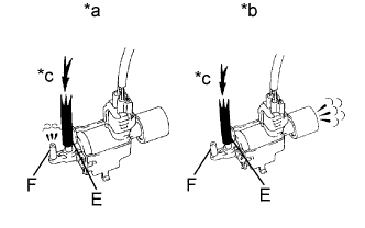
Check the VSV operation when it is operated using the tester.
- OK:
Tester Operation Specified Condition VSV ON Air from port E flows out through port F VSV OFF Air from port E flows out through air filter
Text in Illustration *a VSV is ON *b VSV is OFF *c Air
|
| ||||
| OK | |
| 2.CHECK VACUUM HOSES (VACUUM SWITCHING VALVE - INTAKE AIR CONTROL VALVE, INTAKE MANIFOLD) |
Check the vacuum hoses.
|
| ||||
| OK | |
| 3.INSPECT INTAKE MANIFOLD (INTAKE AIR CONTROL VALVE) |
Inspect the intake air control valve (HILUX_TGN26 RM000000V0000TX_01_0003.html).
|
| ||||
| OK | ||
| ||
| 4.INSPECT VSV FOR ACIS |
Inspect the VSV for ACIS (HILUX_TGN26 RM0000014ZM00LX.html).
|
| ||||
| OK | |
| 5.CHECK HARNESS AND CONNECTOR (VACUUM SWITCHING VALVE - ECM, NO. 1 INTEGRATION RELAY) |
Disconnect the VSV for ACIS connector.
Disconnect the ECM connector.
Remove the No. 1 integration relay from the engine room relay block and junction block assembly.
Measure the resistance according to the value(s) in the table below.
- Standard Resistance:
Tester Connection Condition Specified Condition C139-2 - C129-33 (ACIS) Always Below 1 Ω C139-1 - 1J-5 Always Below 1 Ω C139-2 or C129-33 (ACIS) - Body ground Always 10 kΩ or higher C139-1 or 1J-5 - Body ground Always 10 kΩ or higher
|
| ||||
| OK | |
| 6.GO TO ECM POWER SOURCE CIRCUIT |
Check the ECM power source circuit (HILUX_TGN26 RM000000WZ0077X.html).
|
| ||||
| OK | ||
| ||