Vehicle Exterior. Yaris. Ncp93, 131
Window Glass. Yaris. Ncp93, 131
Power Window Control System (For Sedan) -- Terminals Of Ecu |
| CHECK POWER WINDOW REGULATOR MASTER SWITCH |

Disconnect the G1 power window regulator master switch connector.
Measure the voltage and resistance of the wire harness side connector.
If the result is not as specified, there may be a malfunction on the wire harness side.Terminal No. (Symbol) Wiring Color Terminal Description Condition Specified Condition G1-6 (B) - Body ground GR - Body ground Ignition power supply Ignition switch OFF Below 1 V G1-6 (B) - Body ground GR - Body ground Ignition power supply Ignition switch ON 11 to 14 V G1-1 (E) - Body ground W-B - Body ground Ground Always Below 1 Ω Reconnect the G1 power window regulator master switch connector.
Measure the voltage of the connector.
If the result is not as specified, the master switch may have a malfunction.Terminal No. (Symbol) Wiring Color Terminal Description Condition Specified Condition G1-3 (U) - G1-1 (E) R- W-B Power window motor UP output
(driver side)Ignition switch ON, driver side power window switch OFF → UP (manual operation) Below 1 V → 11 to 14 V G1-4 (D) - G1-1 (E) G - W-B Power window motor DOWN output
(driver side)Ignition switch ON, driver side power window switch OFF → DOWN (manual operation) Below 1 V → 11 to 14 V G1-4 (D) - G1-1 (E) G - W-B Power window motor DOWN output
(driver side)Ignition switch ON, driver side power window fully closed → driver side power window switch DOWN (AUTO operation) → driver side power window fully open Below 1 V → 11 to 14 V → Below 1 V G1-16 (U) - G1-1 (E) W - W-B Power window motor UP output
(passenger side)Ignition switch ON, passenger side power window switch OFF → UP Below 1 V → 11 to 14 V G1-15 (D) - G1-1 (E) P - W-B Power window motor DOWN output
(passenger side)Ignition switch ON, passenger side power window switch OFF → DOWN Below 1 V → 11 to 14 V G1-12 (U) - G1-1 (E) Y - W-B Power window motor UP output
(rear LH)Ignition switch ON, rear LH side power window switch OFF → UP Below 1 V → 11 to 14 V G1-13 (D) - G1-1 (E) B - W-B Power window motor DOWN output
(rear LH)Ignition switch ON, rear LH side power window switch OFF → DOWN Below 1 V → 11 to 14 V G1-10 (U) - G1-1 (E) R - W-B Power window motor UP output
(rear RH)Ignition switch ON, rear RH side power window switch OFF → UP Below 1 V → 11 to 14 V G1-18 (D) - G1-1 (E) G - W-B Power window motor DOWN output
(rear RH)Ignition switch ON, rear RH side power window switch OFF → DOWN Below 1 V → 11 to 14 V Check the AUTO light illumination.
After turning the ignition switch ON, check that the AUTO light illuminates (green).
| CHECK POWER WINDOW SWITCH (PASSENGER SIDE) |

Disconnect the F1 power window switch connector.
Measure the voltage of the wire harness side connector.
If the result is not as specified, there may be a malfunction on the wire harness side.Terminal No. (Symbol) Wiring Color Terminal Description Condition Specified Condition F1-3 (B) - Body ground L - Body ground Ignition power supply Ignition switch OFF Below 1 V F1-3 (B) - Body ground L - Body ground Ignition power supply Ignition switch ON 11 to 14 V F1-1 (D) - Body ground G - Body ground Power window motor DOWN output Ignition switch ON, power window switch OFF → DOWN Below 1 V → 11 to 14 V F1-2 (SD) - Body ground P - Body ground Power window motor DOWN input (Remote) Ignition switch ON, power window master switch OFF → DOWN (Remote) Below 1 V → 11 to 14 V F1-4 (U) - Body ground R - Body ground Power window motor UP output Ignition switch ON, power window switch OFF → UP Below 1 V → 11 to 14 V F1-5 (SU) - Body ground W - Body ground Power window motor UP input (Remote) Ignition switch ON, power window master switch OFF → UP (Remote) Below 1 V → 11 to 14 V Reconnect the F1 power window switch connector.
| CHECK POWER WINDOW SWITCH (REAR DOOR SIDE) |
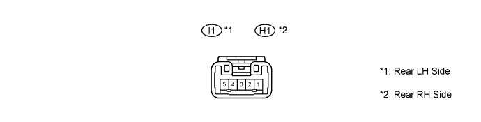
Disconnect the I1 and H1 power window switch connectors.
Measure the voltage of the wire harness side connector.
If the result is not as specified, there may be a malfunction on the wire harness side.Terminal No. (Symbol) Wiring Color Terminal Description Condition Specified Condition 3 (B) - Body ground SB - Body ground Ignition power supply Ignition switch OFF Below 1 V 3 (B) - Body ground SB - Body ground Ignition power supply Ignition switch ON 11 to 14 V 4 (U) - Body ground Y - Body ground Power window motor UP output Ignition switch ON, power window switch OFF → UP Below 1 V → 11 to 14 V 1 (D) - Body ground B - Body ground Power window motor DOWN output Ignition switch ON, power window switch OFF → DOWN Below 1 V → 11 to 14 V 5 (SU) - Body ground R - Body ground Power window motor UP input (Remote) Ignition switch ON, power window master switch OFF → UP (Remote) Below 1 V → 11 to 14 V 2 (SD) - Body ground G - Body ground Power window motor DOWN input (Remote) Ignition switch ON, power window master switch OFF → DOWN (Remote) Below 1 V → 11 to 14 V Reconnect the I1 and H1 power window switch connectors.