Dtc B1412 Ambient Temperature Sensor Circuit
DESCRIPTION
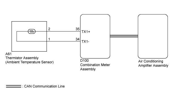
WIRING DIAGRAM
INSPECTION PROCEDURE
CHECK FOR DTC (CAN COMMUNICATION SYSTEM)
READ VALUE USING TECHSTREAM
READ VALUE USING TECHSTREAM
CHECK FOR DTC
REPLACE AIR CONDITIONING AMPLIFIER ASSEMBLY
CHECK FOR DTC
INSPECT THERMISTOR ASSEMBLY (AMBIENT TEMPERATURE SENSOR)
CHECK HARNESS AND CONNECTOR (THERMISTOR ASSEMBLY (AMBIENT TEMPERATURE SENSOR) - AIR CONDITIONING AMPLIFIER ASSEMBLY)
DTC B1412 Ambient Temperature Sensor Circuit |
DESCRIPTION
The thermistor assembly (ambient temperature sensor) is installed in the front part of the cooler condenser assembly to detect the ambient temperature and control the air conditioning auto mode. The sensor connected to the combination meter assembly detects fluctuations in the ambient temperature. This data is used for controlling the room temperature. The sensor sends a signal to the combination meter assembly. The resistance of the thermistor assembly (ambient temperature sensor) changes in accordance with the cooler thermistor temperature (ambient temperature). As the temperature decreases, the resistance increases. As the temperature increases, the resistance decreases.The combination meter assembly applies a voltage (5 V) to the thermistor assembly (ambient temperature sensor) and reads voltage changes as changes in the resistance of the thermistor assembly (ambient temperature sensor). The combination meter assembly sends these signals to the air conditioning amplifier assembly.DTC No.
| DTC Detection Condition
| Trouble Area
|
B1412
| An open or short in the thermistor assembly (ambient temperature sensor) circuit.
| - Thermistor assembly (ambient temperature sensor)
- Harness or connector
- Air conditioning amplifier assembly
- Combination meter assembly
- CAN communication system
|
WIRING DIAGRAM
INSPECTION PROCEDURE
| 1.CHECK FOR DTC (CAN COMMUNICATION SYSTEM) |
Use the Techstream to check if the CAN communication system is functioning normally.
- OK:
- CAN DTC is not output
ResultResult
| Proceed to
|
OK
| A
|
NG (for Hatchback except Separate Type Yaw Rate Sensor)
| B
|
NG (for Hatchback with Separate Type Yaw Rate Sensor)
| C
|
| 2.READ VALUE USING TECHSTREAM |
Connect the Techstream to the DLC3.
Turn the ignition switch to ON.
Turn the Techstream on.
Enter the following menus: Body Electrical / Combination Meter / Data List.
According to the display on the Techstream, read the Data List.
Combination MeterTester Display
| Measurement Item/Range
| Normal Condition
| Diagnostic Note
|
Ambient Temperature
| Ambient temperature sensor /
Min.: -40°C (-40°F)
Max.: 87.5°C (189.5°F)
| Actual ambient temperature is displayed
| -
|
- OK:
- The display is as specified in the normal condition column.
| 3.READ VALUE USING TECHSTREAM |
Connect the Techstream to the DLC3.
Turn the ignition switch to ON.
Turn the Techstream on.
Enter the following menus: Body Electrical / Air Conditioner / Data List.
According to the display on the Techstream, read the Data List.
Air ConditionerTester Display
| Measurement Item/Range
| Normal Condition
| Diagnostic Note
|
Ambient Temp Sensor
| Ambient temperature sensor /
Min.: -23.3°C (-9.94°F)
Max.: 65.95°C (150.71°F)
| Actual ambient temperature is displayed
| -
|
- OK:
- The display is as specified in the normal condition column.
ResultResult
| Proceed to
|
OK (When troubleshooting according to the DTC)
| A
|
OK (When troubleshooting according to Problem Symptoms Table)
| B
|
NG
| C
|
Clear the DTCs (YARIS_NCP93 RM000001GUF06ZX.html).
Check for DTCs (YARIS_NCP93 RM000001GUF06ZX.html).
- OK:
- DTC B1412 is not output
| 5.REPLACE AIR CONDITIONING AMPLIFIER ASSEMBLY |
Temporarily replace the air conditioning amplifier assembly with a new or normally functioning one (YARIS_NCP93 RM00000214000EX.html).
Clear the DTCs (YARIS_NCP93 RM000001GUF06ZX.html).
Check for DTCs (YARIS_NCP93 RM000001GUF06ZX.html).
- OK:
- DTC B1412 is not output
| OK |
|
|
|
| END (AIR CONDITIONING AMPLIFIER ASSEMBLY IS FAULTY) |
|
| 7.INSPECT THERMISTOR ASSEMBLY (AMBIENT TEMPERATURE SENSOR) |
Inspect the thermistor assembly (ambient temperature sensor) (YARIS_NCP93 RM00000201P05LX.html).
| 8.CHECK HARNESS AND CONNECTOR (THERMISTOR ASSEMBLY (AMBIENT TEMPERATURE SENSOR) - AIR CONDITIONING AMPLIFIER ASSEMBLY) |
Disconnect the A61 thermistor assembly (ambient temperature sensor) connector.
Disconnect the D100 combination meter assembly connector.
Measure the resistance according to the value(s) in the table below.
- Standard Resistance:
Tester Connection
| Condition
| Specified Condition
|
A61-2 - D100-35 (TX1+)
| Always
| Below 1 Ω
|
A61-1 - D100-34 (TX1-)
| Always
| Below 1 Ω
|
A61-2 - Body ground
| Always
| 10 kΩ or higher
|
A61-1 - Body ground
| Always
| 10 kΩ or higher
|
| | REPAIR OR REPLACE HARNESS OR CONNECTOR |
|
|