DESCRIPTION
WIRING DIAGRAM
INSPECTION PROCEDURE
INSPECT COMBINATION METER ASSEMBLY (INPUT VOLTAGE)
SYSTEM CHECK
INSPECT COMBINATION METER ASSEMBLY (OUTPUT VOLTAGE)
INSPECT COMBINATION METER ASSEMBLY (INPUT WAVEFORM)
INSPECT COMBINATION METER ASSEMBLY (OUTPUT VOLTAGE)
INSPECT COMBINATION METER ASSEMBLY (INPUT WAVEFORM)
CHECK HARNESS AND CONNECTOR (COMBINATION METER ASSEMBLY - BRAKE ACTUATOR ASSEMBLY)
CHECK HARNESS AND CONNECTOR (COMBINATION METER ASSEMBLY - SPEEDOMETER SENSOR)
CHECK HARNESS AND CONNECTOR (COMBINATION METER ASSEMBLY - INSTRUMENT PANEL JUNCTION BLOCK ASSEMBLY)
INSPECT ECM
SYSTEM CHECK
INSPECT POWER STEERING ECU ASSEMBLY
CHECK HARNESS AND CONNECTOR (INSTRUMENT PANEL JUNCTION BLOCK ASSEMBLY - ECM)
CHECK HARNESS AND CONNECTOR (INSTRUMENT PANEL JUNCTION BLOCK ASSEMBLY - POWER STEERING ECU ASSEMBLY)
METER / GAUGE SYSTEM (for Hatchback) - Speed Signal Circuit |
DESCRIPTION
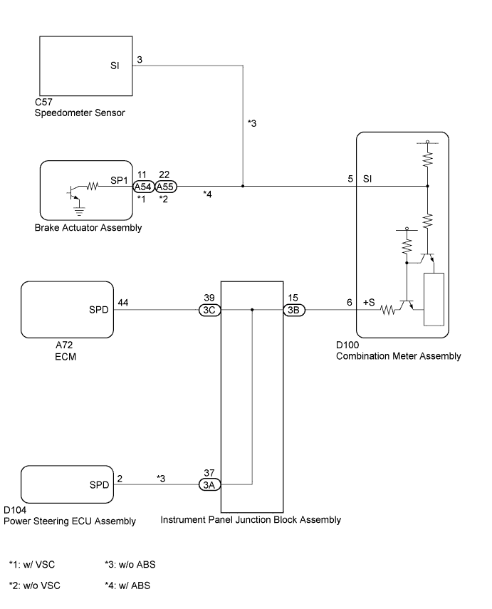
w/ ABS:
- The meter CPU receives vehicle speed signals from this circuit. The vehicle speed sensor detects the voltage that varies according to the vehicle speed. The brake actuator assembly supplies power to the vehicle speed sensor. The brake actuator assembly detects vehicle speed signals based on the pulses of the voltage. The brake actuator assembly transmits vehicle speed signals as pulses to the meter CPU. A voltage of 12 V is output from the combination meter assembly and then input to the brake actuator assembly. The signal is changed to a pulse signal at the transistor in the combination meter assembly.
- A voltage of 12 V or 5 V is output from each ECU or relay and then input to the combination meter assembly.
- Each ECU controls the respective system based on the pulse signal.
- HINT:
- This circuit is used for another system, and is not used for combination meter operation.
w/o ABS:
- The meter CPU receives vehicle speed signals from this circuit. The speedometer sensor detects the voltage that varies according to the vehicle speed. The speedometer sensor detects vehicle speed signals based on the pulses of the voltage. The speedometer sensor transmits vehicle speed signals as pulses to the meter CPU. A voltage of 12 V is output from the combination meter assembly and then input to the speedometer sensor. The signal is changed to a pulse signal at the transistor in the combination meter assembly.
- A voltage of 12 V or 5 V is output from each ECU or relay and then input to the combination meter assembly.
- Each ECU controls the respective system based on the pulse signal.
- HINT:
- This circuit is used for another system, and is not used for combination meter operation.
WIRING DIAGRAM
INSPECTION PROCEDURE
| 1.INSPECT COMBINATION METER ASSEMBLY (INPUT VOLTAGE) |
Disconnect the D100 combination meter assembly connector.
Measure the voltage according to the value(s) in the table below.
- Standard Voltage:
Tester Connection
| Switch Condition
| Specified Condition
|
D100-6 (+S) - Body ground
| Ignition switch ON
| 4.5 to 14 V
|
Text in Illustration*a
| Front view of wire harness connector
(to Combination Meter Assembly)
|
- HINT:
- If any of the ECUs specified in the wiring diagram supplies power to the combination meter assembly, the combination meter assembly will output a waveform.
Reconnect the combination meter assembly connector.
Check the vehicle specifications.
ResultResult
| Proceed to
|
w/ ABS
| A
|
w/o ABS
| B
|
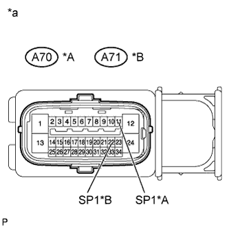
| 3.INSPECT COMBINATION METER ASSEMBLY (OUTPUT VOLTAGE) |
Disconnect the A70*1 or A71*2 brake actuator assembly connector.
Measure the voltage according to the value(s) in the table below.
- Standard Voltage:
Tester Connection
| Switch Condition
| Specified Condition
|
A70-11 (SP1)*1 - Body ground
A71-22 (SP1)*2 - Body ground
| Ignition switch ON
| 11 to 14 V
|
Text in Illustration*A
| w/ VSC
|
*B
| w/o VSC
|
*a
| Front view of wire harness connector
(to brake actuator assembly)
|
Reconnect the A70*1 or A71*2 brake actuator assembly connector.
- *1: w/ VSC
- *2: w/o VSC
| 4.INSPECT COMBINATION METER ASSEMBLY (INPUT WAVEFORM) |
Check the input waveform.
Remove the combination meter assembly with the connector(s) still connected.
Connect an oscilloscope to terminal D100-5 (SI) and body ground.
Turn the ignition switch to ON.
Turn the wheel slowly.
Check the signal waveform according to the condition(s) in the table below.
- Standard:
Item
| Condition
|
Tool setting
| 5 V/DIV., 20 ms./DIV.
|
Condition
| Driving at approx. 20 km/h
|
Text in Illustration*a
| Component with harness connected
(Combination Meter Assembly)
|
*b
| Waveform
|
- OK:
- The waveform is displayed as shown in the illustration.
- HINT:
- As the vehicle speed increases, the cycle of the waveform narrows.
| 5.INSPECT COMBINATION METER ASSEMBLY (OUTPUT VOLTAGE) |
Disconnect the C57 speedometer sensor connector.
Measure the voltage according to the value(s) in the table below.
- Standard Voltage:
Tester Connection
| Switch Condition
| Specified Condition
|
C57-3 (SI) - Body ground
| Ignition switch ON
| 11 to 14 V
|
Text in Illustration*a
| Front view of wire harness connector
(to Speedometer Sensor)
|
Reconnect the C57 speedometer sensor connector.
| 6.INSPECT COMBINATION METER ASSEMBLY (INPUT WAVEFORM) |
Check the input waveform.
Remove the combination meter assembly with the connector(s) still connected.
Connect an oscilloscope to terminal D100-5 (SI) and body ground.
Turn the ignition switch to ON.
Turn the wheel slowly.
Check the signal waveform according to the condition(s) in the table below.
Item
| Condition
|
Tool setting
| 5 V/DIV., 20 ms./DIV.
|
Vehicle condition
| Driving at approx. 20 km/h (12 mph)
|
- OK:
- The waveform is displayed as shown in the illustration.
- HINT:
- As the vehicle speed increases, the cycle of the waveform narrows.
Text in Illustration*a
| Component with harness connected
(Combination Meter Assembly)
|
*b
| Waveform
|
| | REPLACE SPEEDOMETER SENSOR |
|
|
| 7.CHECK HARNESS AND CONNECTOR (COMBINATION METER ASSEMBLY - BRAKE ACTUATOR ASSEMBLY) |
Disconnect the D100 combination meter assembly connector.
Disconnect the A70*1 or A71*2 brake actuator assembly connector.
Measure the resistance according to the value(s) in the table below.
- Standard Resistance:
Tester Connection
| Condition
| Specified Condition
|
D100-5 (SI) - A70-11 (SP1)*1
D100-5 (SI) - A71-22 (SP1)*2
| Always
| Below 1 Ω
|
D100-5 (SI) - Body ground
| Always
| 10 kΩ or higher
|
- *1: w/ VSC
- *2: w/o VSC
| | REPAIR OR REPLACE HARNESS OR CONNECTOR |
|
|
| 8.CHECK HARNESS AND CONNECTOR (COMBINATION METER ASSEMBLY - SPEEDOMETER SENSOR) |
Disconnect the D100 combination meter assembly connector.
Disconnect the C57 speedometer sensor connector.
Measure the resistance according to the value(s) in the table below.
- Standard Resistance:
Tester Connection
| Condition
| Specified Condition
|
C57-3 (SI) - D100-5 (SI)
| Always
| Below 1 Ω
|
C57-3 (SI) - Body ground
| Always
| 10 kΩ or higher
|
| | REPAIR OR REPLACE HARNESS OR CONNECTOR |
|
|
| 9.CHECK HARNESS AND CONNECTOR (COMBINATION METER ASSEMBLY - INSTRUMENT PANEL JUNCTION BLOCK ASSEMBLY) |
Disconnect the 3B instrument panel junction block assembly connector.
Disconnect the D100 combination meter assembly connector.
Measure the resistance according to the value(s) in the table below.
- Standard Resistance:
Tester Connection
| Condition
| Specified Condition
|
D100-6 (+S) - 3B-15
| Always
| Below 1 Ω
|
D100-6 (+S) - Body ground
| Always
| 10 kΩ or higher
|
Reconnect the 3B instrument panel junction block assembly connector.
Reconnect the D100 combination meter assembly connector.
| | REPAIR OR REPLACE HARNESS OR CONNECTOR |
|
|
Disconnect the 3C instrument panel junction block assembly connector.
Measure the voltage according to the value(s) in the table below.
- Standard Voltage:
Tester Connection
| Switch Condition
| Specified Condition
|
3C-39 - Body ground
| Ignition switch ON
| 4.5 to 14 V
|
Text in Illustration*a
| Front view of wire harness connector
(to Instrument Panel Junction Block Assembly)
|
Reconnect the 3C instrument panel junction block assembly connector.
Check the vehicle specifications.
ResultResult
| Proceed to
|
w/ ABS
| A
|
w/o ABS
| B
|
| 12.INSPECT POWER STEERING ECU ASSEMBLY |
Disconnect the 3A instrument panel junction block assembly connector.
Measure the voltage according to the value(s) in the table below.
- Standard Voltage:
Tester Connection
| Switch Condition
| Specified Condition
|
3A-37 - Body ground
| Ignition switch ON
| 4.5 to 14 V
|
Text in Illustration*a
| Front view of wire harness connector
(to Instrument Panel Junction Block Assembly)
|
Reconnect the 3A instrument panel junction block assembly connector.
| 13.CHECK HARNESS AND CONNECTOR (INSTRUMENT PANEL JUNCTION BLOCK ASSEMBLY - ECM) |
Disconnect the 3C instrument panel junction block assembly connector.
Disconnect the A72 ECM connector.
Measure the resistance according to the value(s) in the table below.
- Standard Resistance:
Tester Connection
| Condition
| Specified Condition
|
3C-39 - A72-44 (SPD)
| Always
| Below 1 Ω
|
3C-39 - Body ground
| Always
| 10 kΩ or higher
|
Reconnect the 3C instrument panel junction block assembly connector.
Reconnect the A72 ECM connector.
| | REPAIR OR REPLACE HARNESS OR CONNECTOR |
|
|
| 14.CHECK HARNESS AND CONNECTOR (INSTRUMENT PANEL JUNCTION BLOCK ASSEMBLY - POWER STEERING ECU ASSEMBLY) |
Disconnect the 3A instrument panel junction block assembly connector.
Disconnect the D104 power steering ECU connector.
Measure the resistance according to the value(s) in the table below.
- Standard Resistance:
Tester Connection
| Condition
| Specified Condition
|
3A-37 - D104-2 (SPD)
| Always
| Below 1 Ω
|
3A-37 - Body ground
| Always
| 10 kΩ or higher
|
Reconnect the 3A instrument panel junction block assembly connector.
Reconnect the D104 power steering ECU connector.
| | REPAIR OR REPLACE HARNESS OR CONNECTOR |
|
|