DESCRIPTION
WIRING DIAGRAM
INSPECTION PROCEDURE
CHECK CAN COMMUNICATION SYSTEM
CHECK IF SKID CONTROL ECU CONNECTOR IS SECURELY CONNECTED
INSPECT BATTERY
INSPECT SKID CONTROL ECU (IG1 TERMINAL)
INSPECT SKID CONTROL ECU (GND TERMINAL)
READ VALUE USING TECHSTREAM (PARKING BRAKE SWITCH)
INSPECT BRAKE FLUID LEVEL WARNING SWITCH
CHECK HARNESS AND CONNECTOR (COMBINATION METER - BRAKE FLUID LEVEL WARNING SWITCH)
INSPECT COMBINATION METER ASSEMBLY
REPLACE COMBINATION METER ASSEMBLY
INSPECT COMBINATION METER ASSEMBLY
INSPECT PARKING BRAKE SWITCH
CHECK HARNESS AND CONNECTOR (MAIN BODY ECU - PARKING BRAKE SWITCH)
VEHICLE STABILITY CONTROL SYSTEM (for Sedan) - Brake Warning Light Remains ON |
DESCRIPTION
The skid control ECU is connected to the combination meter via CAN communication.If any of the following is detected, the brake warning light remains on:- The skid control ECU connector is disconnected from the skid control ECU.
- The brake fluid level is insufficient.
- The parking brake is applied.
- EBD operation is not possible.
WIRING DIAGRAM
INSPECTION PROCEDURE
- NOTICE:
- When replacing the brake actuator assembly, perform zero point calibration (YARIS_NCP93 RM000000XHR06QX.html).
| 1.CHECK CAN COMMUNICATION SYSTEM |
Check if CAN communication system DTCs are output (YARIS_NCP93 RM000001D3E00OX.html).
ResultResult
| Proceed to
|
DTC is not output
| A
|
DTC is output
| B
|
| 2.CHECK IF SKID CONTROL ECU CONNECTOR IS SECURELY CONNECTED |
Check if the skid control ECU connector is securely connected.
- OK:
- The connector is securely connected.
| | CONNECT CONNECTOR TO ECU CORRECTLY |
|
|
Check the battery voltage.
- Standard voltage:
- 11 to 14 V
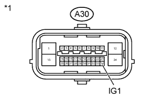
| 4.INSPECT SKID CONTROL ECU (IG1 TERMINAL) |
Disconnect the A30 skid control ECU connector.
Turn the ignition switch to ON.
Measure the voltage according to the value(s) in the table below.
Text in Illustration*1
| Front view of wire harness connector
(to Skid Control ECU)
|
- Standard Voltage:
Tester Connection
| Switch Condition
| Specified Condition
|
A30-34 (IG1) - Body ground
| Ignition switch ON
| 11 to 14 V
|
| | REPAIR OR REPLACE HARNESS OR CONNECTOR (IG1 CIRCUIT) |
|
|
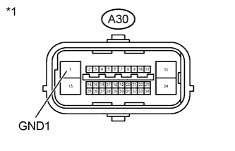
| 5.INSPECT SKID CONTROL ECU (GND TERMINAL) |
Turn the ignition switch off.
Measure the resistance according to the value(s) in the table below.
Text in Illustration*1
| Front view of wire harness connector
(to Skid Control ECU)
|
- Standard Resistance:
Tester Connection
| Condition
| Specified Condition
|
A30-1 (GND1) - Body ground
| Always
| Below 1 Ω
|
| | REPAIR OR REPLACE HARNESS OR CONNECTOR (GND CIRCUIT) |
|
|
| 6.READ VALUE USING TECHSTREAM (PARKING BRAKE SWITCH) |
Reconnect the skid control ECU connector.
Connect the Techstream to the DLC3.
Turn the ignition switch to ON.
Enter the following menus: Chassis / ABS/VSC/TRAC / Data List.
ABS/VSC/TRAC (Skid Control ECU)Tester Display
| Measurement Item/Range
| Normal Condition
| Diagnostic Note
|
Parking Brake SW
| Parking brake switch / ON or OFF
| ON: Parking brake applied
OFF: Parking brake released
| -
|
Using the Techstream, check the input of the switch operation when the parking brake pedal is operated.
- OK:
- When the parking brake is operated, the display changes as shown above.
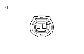
| 7.INSPECT BRAKE FLUID LEVEL WARNING SWITCH |
Turn the ignition switch off.
Text in Illustration*1
| Component without harness connected
(Brake Fluid Level Warning Switch)
|
Remove the reservoir filler cap and strainer.
Disconnect the brake fluid level warning switch connector.
Measure the resistance according to the value(s) in the table below.
- HINT:
- A float is located inside the reservoir. Its position can be changed by increasing or decreasing the level of brake fluid.
- Standard Resistance:
Tester Connection
| Switch Condition
| Specified Condition
|
1 - 2
| Switch OFF (Float up)
| 10 kΩ or higher
|
1 - 2
| Switch ON (Float down)
| Below 1 Ω
|
- HINT:
- If there is no problem after finishing the above check, adjust the brake fluid level to the MAX level.
| 8.CHECK HARNESS AND CONNECTOR (COMBINATION METER - BRAKE FLUID LEVEL WARNING SWITCH) |
Disconnect the D76 or D2 combination meter connector.
Measure the resistance according to the value(s) in the table below.
- Standard Resistance:
Tester Connection
| Condition
| Specified Condition
|
D76-2 (SW) - A10-1
| Always
| Below 1 Ω
|
D76-2 (SW) - Body ground
| Always
| 10 kΩ or higher
|
A10-2 - Body ground
| Always
| Below 1 Ω
|
| | REPAIR OR REPLACE HARNESS OR CONNECTOR |
|
|
| 9.INSPECT COMBINATION METER ASSEMBLY |
Connect the Techstream to the DLC3.
Perform Active Test of the combination meter using the Techstream (YARIS_NCP93 RM000001DAT00FX.html).
- OK:
- The brake warning light turns ON or OFF in accordance with the Techstream.
- HINT:
- Reinstall the connectors and restore the vehicle to its prior condition before checking the combination meter.
| 10.REPLACE COMBINATION METER ASSEMBLY |
Turn the ignition switch off.
Replace the combination meter (YARIS_NCP93 RM000000IN001JX.html).
| 11.INSPECT COMBINATION METER ASSEMBLY |
Connect the Techstream to the DLC3.
Perform Active Test of the combination meter using the Techstream (YARIS_NCP93 RM000001DAT00FX.html).
- OK:
- The brake warning light turns ON or OFF in accordance with the Techstream.
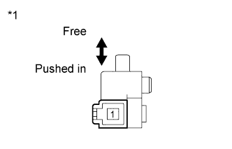
| 12.INSPECT PARKING BRAKE SWITCH |
Turn the ignition switch off.
Text in Illustration*1
| Component without harness connected
(Parking Brake Switch)
|
Disconnect the parking brake switch connector.
Measure the resistance according to the value(s) in the table below.
- Standard Resistance:
Tester Connection
| Switch Condition
| Specified Condition
|
1 - Body ground
| Parking brake switch ON
(Switch pin free)
| Below 1 Ω
|
1 - Body ground
| Parking brake switch OFF
(Switch pin pushed in)
| 10 kΩ or higher
|
| 13.CHECK HARNESS AND CONNECTOR (MAIN BODY ECU - PARKING BRAKE SWITCH) |
Disconnect the 4C main body ECU connector.
Measure the resistance according to the value(s) in the table below.
- Standard Resistance:
Tester Connection
| Condition
| Specified Condition
|
4C-2 (PKB) - D21-1
| Always
| Below 1 Ω
|
4C-2 (PKB) - Body ground
| Always
| 10 kΩ or higher
|
| | REPAIR OR REPLACE HARNESS OR CONNECTOR |
|
|