Dtc C2198/98 Initialization Switch (For Test Mode Dtc)
DESCRIPTION
WIRING DIAGRAM
INSPECTION PROCEDURE
INSPECT TIRE PRESSURE WARNING RESET SWITCH
CHECK HARNESS AND CONNECTOR (RESET SWITCH - TIRE PRESSURE WARNING ECU AND RECEIVER)
DTC C2198/98 Initialization Switch (for Test Mode DTC) |
DESCRIPTION
During test mode, when the tire pressure warning reset switch is on, the tire pressure warning light comes on and when the tire pressure warning reset switch is off, the tire pressure warning light blinks at 0.125 second intervals.DTC No.
| DTC Detection Condition
| Trouble Area
|
C2198/98
| Test mode procedure is performed.
| - Tire pressure warning reset switch
- Wire harness or connector
- Tire pressure warning ECU and receiver
|
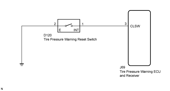
WIRING DIAGRAM
INSPECTION PROCEDURE
- NOTICE:
- When replacing the tire pressure warning ECU and receiver, read the transmitter IDs stored in the old ECU using the Techstream and write them down before removal.
- It is necessary to perform initialization (YARIS_NCP93 RM000000XMZ073X.html) after registration (YARIS_NCP93 RM000000XN107WX.html) of the transmitter IDs into the tire pressure warning ECU and receiver if the ECU has been replaced.
- When replacing the tire pressure warning ECU and receiver on vehicles equipped with the wireless door lock control system, be sure to perform Registration of Recognition Code to register the transmitter IDs after ECU replacement (YARIS_NCP93 RM0000023D302UX.html).
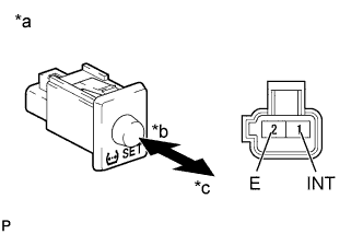
| 1.INSPECT TIRE PRESSURE WARNING RESET SWITCH |
Disconnect the tire pressure warning reset switch connector.
Measure the resistance according to the value(s) in the table below.
- Standard Resistance:
Tester Connection
| Switch Condition
| Specified Condition
|
1 (INT) - 2 (E)
| ON
| Below 1 Ω
|
OFF
| 10 kΩ or higher
|
Text in Illustration*a
| Component without harness connected
(Tire Pressure Warning Reset Switch)
|
*b
| ON
|
*c
| OFF
|
| 2.CHECK HARNESS AND CONNECTOR (RESET SWITCH - TIRE PRESSURE WARNING ECU AND RECEIVER) |
Disconnect the tire pressure warning reset switch D120 connector and tire pressure warning ECU and receiver J69 connector.
Measure the resistance according to the value(s) in the table below.
- Standard Resistance:
Tester Connection
| Switch Condition
| Specified Condition
|
J69-3 (CLSW) - D120-1 (INT)
| Always
| Below 1 Ω
|
J69-3 (CLSW) - Body ground
| 10 kΩ or higher
|
D120-2 (E) - Body ground
| Below 1 Ω
|
| | REPAIR OR REPLACE HARNESS OR CONNECTOR |
|
|