Rear Axle Beam (For Hatchback) Installation
TEMPORARILY TIGHTEN REAR AXLE BEAM ASSEMBLY
INSTALL REAR COIL SPRING LH
INSTALL REAR COIL SPRING RH
TEMPORARILY TIGHTEN REAR SHOCK ABSORBER ASSEMBLY LH
TEMPORARILY TIGHTEN REAR SHOCK ABSORBER ASSEMBLY RH
INSTALL REAR AXLE HUB AND BEARING ASSEMBLY (for Rear Drum Brake)
INSTALL REAR AXLE HUB AND BEARING ASSEMBLY (for Rear Disc Brake)
INSPECT REAR AXLE HUB BEARING BACKLASH (for Rear Drum Brake)
INSPECT REAR AXLE HUB BEARING BACKLASH (for Rear Disc Brake)
INSPECT REAR AXLE HUB RUNOUT (for Rear Drum Brake)
INSPECT REAR AXLE HUB RUNOUT (for Rear Disc Brake)
INSTALL REAR BRAKE DRUM SUB-ASSEMBLY (for Rear Drum Brake)
INSTALL REAR DISC (for Rear Disc Brake)
INSTALL REAR DISC BRAKE CYLINDER MOUNTING LH (for Rear Disc Brake)
INSTALL REAR DISC BRAKE CYLINDER MOUNTING RH (for Rear Disc Brake)
INSTALL REAR DISC BRAKE PAD (for Rear Disc Brake)
INSTALL REAR DISC BRAKE CYLINDER ASSEMBLY LH (for Rear Disc Brake)
INSTALL REAR DISC BRAKE CYLINDER ASSEMBLY RH (for Rear Disc Brake)
INSTALL NO. 3 PARKING BRAKE CABLE ASSEMBLY
INSTALL NO. 2 PARKING BRAKE CABLE ASSEMBLY
INSTALL NO. 4 REAR BRAKE TUBE (for Rear Drum Brake)
INSTALL NO. 3 REAR BRAKE TUBE (for Rear Drum Brake)
INSTALL NO. 4 REAR BRAKE TUBE (for Rear Disc Brake)
INSTALL NO. 3 REAR BRAKE TUBE (for Rear Disc Brake)
INSTALL SKID CONTROL SENSOR WIRE LH (w/ ABS)
INSTALL SKID CONTROL SENSOR WIRE RH (w/ ABS)
INSTALL REAR WHEEL
STABILIZE SUSPENSION
FULLY TIGHTEN REAR AXLE BEAM ASSEMBLY
FULLY TIGHTEN REAR SHOCK ABSORBER ASSEMBLY LH
FULLY TIGHTEN REAR SHOCK ABSORBER ASSEMBLY RH
BLEED BRAKE LINE
BLEED CLUTCH LINE (for Manual Transaxle)
INSPECT REAR WHEEL ALIGNMENT
CHECK SPEED SENSOR SIGNAL (w/ ABS)
CHECK SPEED SENSOR SIGNAL (w/ VSC)
Rear Axle Beam (For Hatchback) -- Installation |
| 1. TEMPORARILY TIGHTEN REAR AXLE BEAM ASSEMBLY |
Support the rear axle beam assembly with an engine lift.
Install the rear axle beam assembly onto the vehicle and provisionally tighten the 2 bolts.
| 2. INSTALL REAR COIL SPRING LH |
Install the rear coil spring lower insulator LH onto the rear axle beam assembly.
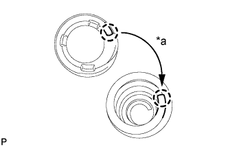
Install the rear coil spring upper insulator LH so that its gap fits onto the end of rear coil spring LH.
Text in Illustration*a
| Fit
|
Install the rear coil spring LH onto the rear axle beam assembly.
Text in Illustration
| Paint Mark
|
- NOTICE:
- The paint mark of the rear coil spring LH should be towards the underside and rear side of the vehicle.
| 3. INSTALL REAR COIL SPRING RH |
- HINT:
- Use the same procedure for the RH side as for the LH side.
| 4. TEMPORARILY TIGHTEN REAR SHOCK ABSORBER ASSEMBLY LH |
Support the rear axle beam with a jack. Insert a wooden block between the jack and the rear axle spring seat to prevent damage.
Jack up the rear axle beam slowly, and provisionally install the rear shock absorber assembly (lower side) with the bolt and nut onto the rear axle beam assembly.
Install the suspension rear support and rear shock absorber cushion retainer.
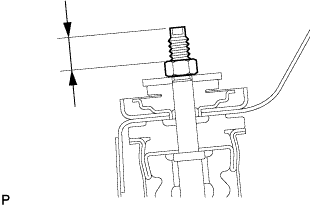
While holding the piston rod, install a new nut (lower nut) to the specified standard.
- Standard:
- 15 to 18 mm (0.591 to 0.709 in.)
Install a new nut (upper nut) onto the lower nut.
Hold the lower nut and tighten the upper nut against it.
- Torque:
- 25 N*m{250 kgf*cm, 18 ft.*lbf}
| 5. TEMPORARILY TIGHTEN REAR SHOCK ABSORBER ASSEMBLY RH |
- HINT:
- Use the same procedure for the RH side as for the LH side.
| 6. INSTALL REAR AXLE HUB AND BEARING ASSEMBLY (for Rear Drum Brake) |
Install the axle hub and bearing onto the axle beam with the 4 bolts.
- Torque:
- 90 N*m{918 kgf*cm, 66 ft.*lbf}
| 7. INSTALL REAR AXLE HUB AND BEARING ASSEMBLY (for Rear Disc Brake) |
Install the dust cover and the axle hub and bearing onto the axle beam with the 4 bolts.
- Torque:
- 90 N*m{918 kgf*cm, 66 ft.*lbf}
| 8. INSPECT REAR AXLE HUB BEARING BACKLASH (for Rear Drum Brake) |
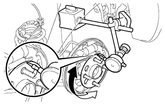
Using a dial indicator, check the backlash near the center of the axle hub.
- Maximum:
- 0.05 mm (0.00197 in.)
If the runout exceeds the maximum, replace the rear axle hub and bearing assembly.
| 9. INSPECT REAR AXLE HUB BEARING BACKLASH (for Rear Disc Brake) |
Using a dial indicator, check the backlash near the center of the axle hub.
- Maximum:
- 0.05 mm (0.00197 in.)
If the runout exceeds the maximum, replace the rear axle hub and bearing assembly.
| 10. INSPECT REAR AXLE HUB RUNOUT (for Rear Drum Brake) |
Using a dial indicator, check the runout of the surface of the axle hub.
- Maximum:
- 0.07 mm (0.00276 in.)
If the runout exceeds the maximum, replace the rear axle hub and bearing assembly.
| 11. INSPECT REAR AXLE HUB RUNOUT (for Rear Disc Brake) |
Using a dial indicator, check the runout of the surface of the axle hub.
- Maximum:
- 0.07 mm (0.00276 in.)
If the runout exceeds the maximum, replace the rear axle hub and bearing assembly.
| 12. INSTALL REAR BRAKE DRUM SUB-ASSEMBLY (for Rear Drum Brake) |
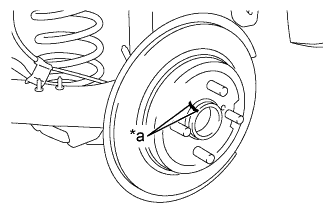
| 13. INSTALL REAR DISC (for Rear Disc Brake) |
Align the matchmarks of the rear disc and axle hub and install the rear disc.
Text in Illustration*a
| Matchmark
|
- NOTICE:
- When replacing the disc with a new one, select the installation position where the rear disc has minimal runout.
| 14. INSTALL REAR DISC BRAKE CYLINDER MOUNTING LH (for Rear Disc Brake) |
Install the rear disc brake cylinder mounting to the axle beam with the 2 bolts.
- Torque:
- 57 N*m{585 kgf*cm, 42 ft.*lbf}
| 15. INSTALL REAR DISC BRAKE CYLINDER MOUNTING RH (for Rear Disc Brake) |
- HINT:
- Use the same procedure for the RH side as for the LH side.
| 16. INSTALL REAR DISC BRAKE PAD (for Rear Disc Brake) |
Install the 2 rear disc brake pads to the rear disc brake cylinder mounting.
- NOTICE:
- There should be no oil or grease on the friction surfaces of the disc brake pads or the rear disc.
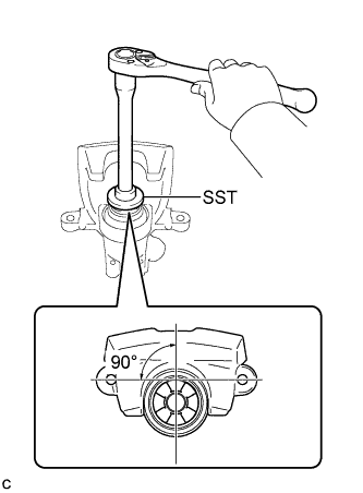
| 17. INSTALL REAR DISC BRAKE CYLINDER ASSEMBLY LH (for Rear Disc Brake) |
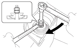
To compensate for pad wear when reusing the pad, use SST to push and turn the piston (LH side: counterclockwise, RH side: clockwise) to the position where the protrusion on the pad lines up properly with the piston groove.
- SST
- 09719-12010(09719-01030)
- HINT:
- Place the disc between the 2 brake pads and determine the piston return value.
Hold the rear disc brake pad guide pin, and install the rear disc brake cylinder assembly to the rear disc brake cylinder mounting with the 2 bolts.
- Torque:
- 34 N*m{350 kgf*cm, 25 ft.*lbf}
| 18. INSTALL REAR DISC BRAKE CYLINDER ASSEMBLY RH (for Rear Disc Brake) |
- HINT:
- Use the same procedure for the RH side as for the LH side.
| 19. INSTALL NO. 3 PARKING BRAKE CABLE ASSEMBLY |
Install the No. 3 parking brake cable assembly with the bolt and a new clamp.
- Torque:
- 6.0 N*m{61 kgf*cm, 53 in.*lbf}
| 20. INSTALL NO. 2 PARKING BRAKE CABLE ASSEMBLY |
- HINT:
- Use the same procedure for the RH side as for the LH side.
| 21. INSTALL NO. 4 REAR BRAKE TUBE (for Rear Drum Brake) |
Install the No. 4 rear brake tube onto the rear axle beam assembly with the nut.
- Torque:
- 5.0 N*m{51 kgf*cm, 48 in.*lbf}
Connect the rear flexible hose LH to the rear axle beam assembly with a new clip.
Using a union nut wrench (10 mm), separate the No. 4 rear brake tube while holding the rear flexible hose LH with a wrench.
- Torque:
- 15 N*m{155 kgf*cm, 11 ft.*lbf}
- NOTICE:
- Use the formula to calculate special torque values for situations where a union nut wrench is combined with a torque wrench (YARIS_NCP93 RM00000482L007X.html).
| 22. INSTALL NO. 3 REAR BRAKE TUBE (for Rear Drum Brake) |
- HINT:
- Use the same procedure for the RH side as for the LH side.
| 23. INSTALL NO. 4 REAR BRAKE TUBE (for Rear Disc Brake) |
Install the No. 4 rear brake tube onto the rear axle beam assembly with the nut.
- Torque:
- 5.0 N*m{51 kgf*cm, 48 in.*lbf}
Connect the 2 rear flexible hose LH to the rear axle beam assembly with 2 new clips.
Using a union nut wrench (10 mm), install the No. 4 rear brake tube to the rear flexible hose LH while holding the rear flexible hose LH with a wrench.
- Torque:
- 15 N*m{155 kgf*cm, 11 ft.*lbf}
- NOTICE:
- Use the formula to calculate special torque values for situations where a union nut wrench is combined with a torque wrench (YARIS_NCP93 RM00000482L007X.html).
| 24. INSTALL NO. 3 REAR BRAKE TUBE (for Rear Disc Brake) |
- HINT:
- Use the same procedure for the RH side as for the LH side.
| 25. INSTALL SKID CONTROL SENSOR WIRE LH (w/ ABS) |
Install the skid control sensor wire LH onto the rear axle beam assembly with the nut.
- Torque:
- 6.0 N*m{61 kgf*cm, 53 in.*lbf}
Connect the skid control sensor wire LH connector.
| 26. INSTALL SKID CONTROL SENSOR WIRE RH (w/ ABS) |
- HINT:
- Use the same procedure for the RH side as for the LH side.
- Torque:
- 103 N*m{1050 kgf*cm, 76 ft.*lbf}
Lower the vehicle from the jack.
Bounce the vehicle up and down several times to stabilize the suspension.
| 29. FULLY TIGHTEN REAR AXLE BEAM ASSEMBLY |
Suspend the jack on the rear axle spring seat and adjust the length of the rear shock absorber assembly to the reference value.
Text in Illustration*a
| RH Side
|
*b
| LH Side
|
- Length of shock absorber:
- 220 mm (8.66 in.)
Fully tighten the 2 bolts.
- Torque:
- 90 N*m{918 kgf*cm, 66 ft.*lbf}
| 30. FULLY TIGHTEN REAR SHOCK ABSORBER ASSEMBLY LH |
Fully tighten the rear shock absorber assembly (lower side) with the bolt.
- Torque:
- 49 N*m{500 kgf*cm, 36 ft.*lbf}
| 31. FULLY TIGHTEN REAR SHOCK ABSORBER ASSEMBLY RH |
- HINT:
- Use the same procedure for the RH side as for the LH side.
(YARIS_NCP93 RM000003WYV009X.html)
| 33. BLEED CLUTCH LINE (for Manual Transaxle) |
(YARIS_NCP93 RM0000010R704XX.html)
| 34. INSPECT REAR WHEEL ALIGNMENT |
(YARIS_NCP93 RM000001BCO01RX.html)
| 35. CHECK SPEED SENSOR SIGNAL (w/ ABS) |
(YARIS_NCP93 RM000000XHT097X.html)
| 36. CHECK SPEED SENSOR SIGNAL (w/ VSC) |
(YARIS_NCP93 RM000000XHT098X.html)