TYPICAL MALFUNCTION THRESHOLDS
CHECK OTHER DTCS OUTPUT (IN ADDITION TO DTC P2714)
INSPECT SHIFT SOLENOID VALVE SLT
INSPECT TRANSMISSION VALVE BODY ASSEMBLY
INSPECT TORQUE CONVERTER CLUTCH ASSEMBLY
DTC P2714 Pressure Control Solenoid "D" Performance (Shift Solenoid Valve SLT) |
DESCRIPTION
Shift solenoid valve SLT controls the transmission line pressure for smooth transmission operation based on signals from the throttle position sensor and vehicle speed sensor. The ECM adjusts the current to shift solenoid valve SLT to control the hydraulic line pressure coming from the primary regulator valve. Appropriate line pressure assures smooth shifting with varying engine outputs.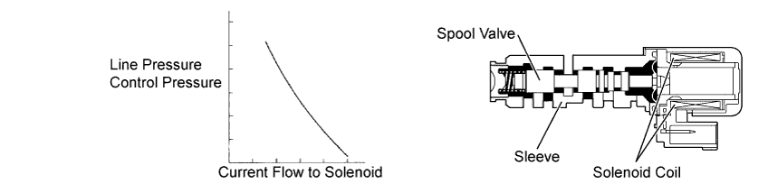
| DTC No. | DTC Detection Condition | Trouble Area |
| P2714 | ECM detects malfunction on SLT (ON side) according to difference in revolutions of turbine (input) and output shaft (2-trip detection logic). |
|
MONITOR DESCRIPTION
In any forward position, when the difference between the revolutions of the turbine and output shaft exceeds the specified value (varies with output speed) determined by the ECM, the ECM illuminates the MIL and stores the DTC. When shift solenoid valve SLT remains on, the oil pressure goes down and the clutch engagement force decreases.MONITOR STRATEGY
| Related DTCs | P2714: Shift solenoid valve SLT/ON malfunction |
| Required sensors/Components | Shift solenoid valve SLT, Speed sensor (NT), Speed sensor (SPD) |
| Frequency of operation | Continuous |
| Duration | 1.0 second |
| MIL operation | 2 driving cycles |
| Sequence of operation | None |
TYPICAL ENABLING CONDITIONS
The following conditions are common to ON malfunctions (a), (b), (c) and (d).| Transmission shift position | D |
| Time after shifting N to D | 4.5 seconds or more |
| ATF (Automatic Transmission Fluid) temperature | -10°C (14°F) or more |
| Turbine Speed Sensor circuit | No circuit malfunction (P0717) |
| Vehicle Speed Sensor "A" circuit | No circuit malfunction (P0500) |
| Transmission Fluid Temperature Sensor "A" circuit | No circuit malfunction (P0710*1, P0712, P0713) |
| Shift Solenoid "A" (S1) circuit | No circuit malfunction (P0973, P0974) |
| Shift Solenoid "B" (S2) circuit | No circuit malfunction (P0976, P0977) |
| Torque Converter Clutch Pressure Control Solenoid (SLU) circuit | No circuit malfunction (P2759) |
| Pressure Control Solenoid "D" (SLT) circuit | No circuit malfunction (P2716) |
| Electronic Throttle Control System | No circuit malfunction (P0120, P0121, P0122, P0123, P0220, P0222, P0223, P0604, P0606, P0607*1, P060A, P060D, P060E, P0657, P1607, P2102, P2103, P2111, P2112, P2118, P2119, P2135) |
- *1: for Mexico models
| ECM gearshift command | 1st |
| Input (turbine) speed | 200 rpm or more |
| Output speed | 300 rpm or more |
| ECM gearshift command | 2nd |
| Input (turbine) speed | 200 rpm or more |
| Output speed | 300 rpm or more |
| ECM gearshift command | 3rd |
| Input (turbine) speed | 200 rpm or more |
| Output speed | 300 rpm or more |
| ECM gearshift command | 4th |
| Input (turbine) speed | 200 rpm or more |
| Output speed | 300 rpm or more |
TYPICAL MALFUNCTION THRESHOLDS
- Detection condition: Total accumulated time of ON malfunctions (a), (b), (c) and (d) is 1 second or more
| NT - NO x 1st gear ratio NT: Input (turbine) speed NO: Internal counter shaft speed | More than 300 rpm at output speed of 1000 rpm (Conditions vary with output speed) |
| Duration | 0.85 seconds or more |
| NT - NO x 2nd gear ratio | More than 300 rpm at output speed of 1000 rpm (Conditions vary with output speed) |
| Duration | 0.85 seconds or more |
| NT - NO x 3rd gear ratio | More than 300 rpm at output speed of 1000 rpm (Conditions vary with output speed) |
| Duration | 0.85 seconds or more |
| NT - NO x 4th gear ratio | More than 300 rpm at output speed of 1000 rpm (Conditions vary with output speed) |
| Duration | 0.85 seconds or more |
INSPECTION PROCEDURE
- NOTICE:
- Perform the universal trip to clear permanent DTCs (YARIS_NCP93 RM000000W770MGX.html).
| ACTIVE TEST |
- HINT:
- Using the Techstream to perform Active Tests allows relays, VSVs, actuators and other items to be operated without removing any parts. This non-intrusive functional inspection can be very useful because intermittent operation may be discovered before parts or wiring is disturbed. Performing Active Tests early in troubleshooting is one way to save diagnostic time. Data List information can be displayed while performing Active Tests.
Warm up the engine.
Turn the ignition switch off.
Connect the Techstream to the DLC3.
Turn the ignition switch to ON.
Turn the Techstream on.
Enter the following menus: Powertrain / Engine and ECT / Active Test.
In accordance with the display on the Techstream, perform the Active Test.
*: Activate the Solenoid (SLT) in the Active Test is performed to check the line pressure changes by connecting SST to the automatic transaxle, which is used in the Hydraulic Test (YARIS_NCP93 RM000000W7B0IJX.html) as well.Tester Display Test Part Control Range Diagnostic Note Activate the Solenoid (SLT)* [Test Details]
Operate shift solenoid SLT and raise line pressure.- HINT:
- OFF: Line pressure up (when active test of Solenoid SLT is performed, ECM turns off SLT solenoid)
- ON: No action (normal operation)
ON/OFF [Vehicle Condition] - Vehicle Stopped
- Engine idling
- HINT:
- The pressure values in Active Test and Hydraulic Test are different from each other.
| 1.CHECK OTHER DTCS OUTPUT (IN ADDITION TO DTC P2714) |
Connect the Techstream to the DLC3.
Turn the ignition switch to ON.
Turn the Techstream on.
Enter the following menus: Powertrain / Engine and ECT / Trouble Codes.
Read the DTCs using the Techstream.
Result Result Proceed to Only P2714 is output A P2714 and other DTCs are output B - HINT:
- If any other DTCs besides P2714 are output, perform troubleshooting for those DTCs first.
|
| ||||
| A | |
| 2.INSPECT SHIFT SOLENOID VALVE SLT |
 |
Remove shift solenoid valve SLT.
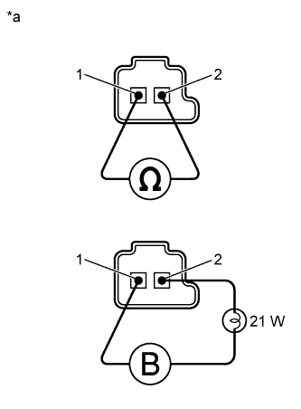
Measure the resistance according to the value(s) in the table below.
- Standard Resistance:
Tester Connection Condition Specified Condition 1 - 2 20°C (68°F) 5.0 to 5.6 Ω
Connect the positive (+) lead with a 21 W bulb to terminal 2 and the negative (-) lead to terminal 1 of the solenoid valve connector, then check the movement of the valve.
- OK:
- The solenoid makes operating sounds.
Text in Illustration *a Component without harness connected
(Shift Solenoid Valve SLT)
|
| ||||
| OK | |
| 3.INSPECT TRANSMISSION VALVE BODY ASSEMBLY |
- OK:
- There are no foreign objects on any valves and they operate smoothly.
|
| ||||
| OK | |
| 4.INSPECT TORQUE CONVERTER CLUTCH ASSEMBLY |
- OK:
- The torque converter clutch operates normally.
|
| ||||
| OK | ||
| ||