Navigation System Illumination Circuit
DESCRIPTION
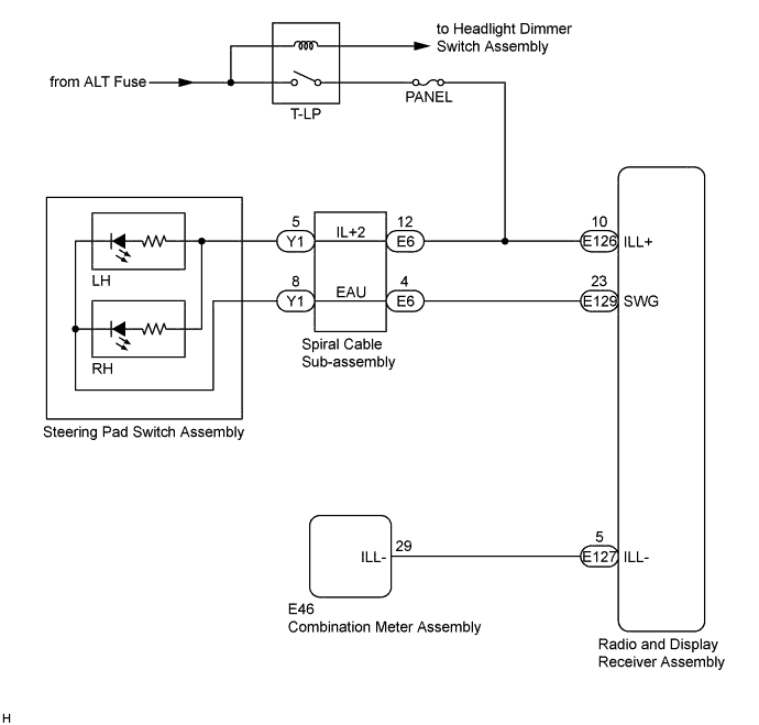
WIRING DIAGRAM
INSPECTION PROCEDURE
CHECK ILLUMINATION
CHECK HARNESS AND CONNECTOR (ILLUMINATION SIGNAL)
INSPECT STEERING PAD SWITCH ASSEMBLY
INSPECT SPIRAL CABLE SUB-ASSEMBLY
CHECK HARNESS AND CONNECTOR (SPIRAL CABLE SUB-ASSEMBLY - BODY GROUND)
CHECK HARNESS AND CONNECTOR (ILLUMINATION SIGNAL)
CHECK HARNESS AND CONNECTOR (RADIO AND DISPLAY RECEIVER ASSEMBLY - COMBINATION METER ASSEMBLY)
NAVIGATION SYSTEM - Illumination Circuit |
DESCRIPTION
Power is supplied to the radio and display receiver assembly and steering pad switch assembly illumination when the light control switch is in the tail or head position.
WIRING DIAGRAM
INSPECTION PROCEDURE
- NOTICE:
- The vehicle is equipped with a Supplemental Restraint System (SRS) which includes components such as airbags. Before servicing (including removal or installation of parts), be sure to read the precaution for Supplemental Restraint System (COROLLA_ZRE142 RM000000KT10H0X.html).
- Inspect the fuses for circuits related to this system before performing the following inspection procedure.
Check if the illumination for the radio and display receiver assembly, steering pad switch assembly, heater control switch or others (hazard switch, transmission control switch, etc.) comes on when the light control switch is turned to the head or tail position.
- Result:
Result
| Proceed to
|
Illumination comes on for all components except steering pad switch assembly.
| A
|
Illumination comes on for all components except radio and display receiver assembly.
| B
|
Illumination comes on only for steering pad switch assembly.
| C
|
No illumination comes on (radio and display receiver assembly, hazard switch, heater control switch, etc.).
| D
|
| 2.CHECK HARNESS AND CONNECTOR (ILLUMINATION SIGNAL) |
Disconnect the spiral cable sub-assembly connector.
Measure the voltage according to the value(s) in the table below.
- Standard Voltage:
Tester Connection
| Condition
| Specified Condition
|
E6-12 (IL+2) - Body ground
| Light control switch in the tail or head position
| 11 to 14 V
|
| | REPAIR OR REPLACE HARNESS OR CONNECTOR |
|
|
| 3.INSPECT STEERING PAD SWITCH ASSEMBLY |
Disconnect the steering pad switch assembly connector (for Type A).
Connect a battery positive (+) lead to terminal IL+2 and a negative (-) lead to terminal EAU of the steering pad switch assembly connector.
Disconnect the steering pad switch assembly connector (for Type B).
Connect a battery positive (+) lead to terminal IL+2 and a negative (-) lead to terminal EAU of the steering pad switch assembly connector.
Check if the illumination for the steering pad switch assembly comes on.
- OK:
- Illumination for the steering pad switch assembly comes on.
Text in Illustration*A
| for Type A
| *B
| for Type B
|
*a
| Component without harness connected
(Steering Pad Switch Assembly)
| -
| -
|
| 4.INSPECT SPIRAL CABLE SUB-ASSEMBLY |
Disconnect the steering pad switch assembly connector.
Disconnect the spiral cable sub-assembly connector.
Measure the resistance according to the value(s) in the table below.
- Standard Resistance:
Tester Connection
| Condition
| Specified Condition
|
Y1-5 (IL+2) - E6-12 (IL+2)
| Center
| Below 1 Ω
|
2.5 rotations to the left
|
2.5 rotations to the right
|
Y1-8 (EAU) - E6-4 (EAU)
| Center
| Below 1 Ω
|
2.5 rotations to the left
|
2.5 rotations to the right
|
After setting the spiral cable sub-assembly to the center position, rotate the spiral cable sub-assembly 2.5 times clockwise. Then while rotating the spiral cable sub-assembly 5 times counterclockwise, measure the resistance as shown in the table below.
- Standard Resistance:
Tester Connection
| Condition
| Specified Condition
|
Y1-5 (IL+2) - E6-12 (IL+2)
| Always
| Below 1 Ω
|
Y1-8 (EAU) - E6-4 (EAU)
| Always
| Below 1 Ω
|
- NOTICE:
- The spiral cable sub-assembly is an important part of the SRS airbag system. Incorrect removal or installation of the spiral cable sub-assembly may prevent the airbag from deploying. Refer to the pages shown in the brackets.
- As the spiral cable sub-assembly may break, do not rotate the spiral cable sub-assembly more than the specified amount.
- HINT:
- Removal (COROLLA_ZRE142 RM000000UWD09PX.html)
Text in Illustration*a
| Component without harness connected
(Spiral Cable Sub-assembly)
|
*b
| Steering Pad Switch Assembly Side
|
*c
| Vehicle Side
|
| 5.CHECK HARNESS AND CONNECTOR (SPIRAL CABLE SUB-ASSEMBLY - BODY GROUND) |
Disconnect the spiral cable sub-assembly connectors.
Measure the resistance according to the value(s) in the table below.
- Standard Resistance:
Tester Connection
| Condition
| Specified Condition
|
E6-4 (EAU) - Body ground
| Always
| Below 1 Ω
|
| | REPAIR OR REPLACE HARNESS OR CONNECTOR |
|
|
| 6.CHECK HARNESS AND CONNECTOR (ILLUMINATION SIGNAL) |
Disconnect the radio and display receiver assembly connector.
Measure the voltage according to the value(s) in the table below.
- Standard Voltage:
Tester Connection
| Condition
| Specified Condition
|
E126-10 (ILL+) - Body ground
| Light control switch in the tail or head position
| 11 to 14 V
|
| | REPAIR OR REPLACE HARNESS OR CONNECTOR |
|
|
| 7.CHECK HARNESS AND CONNECTOR (RADIO AND DISPLAY RECEIVER ASSEMBLY - COMBINATION METER ASSEMBLY) |
Disconnect the radio and display receiver assembly connector.
Disconnect the combination meter assembly connector.
Measure the resistance according to the value(s) in the table below.
- Standard Resistance:
Tester Connection
| Condition
| Specified Condition
|
E127-5 (ILL-) - E46-29 (ILL-)
| Always
| Below 1 Ω
|
E127-5 (ILL-) - Body ground
| Always
| 10 kΩ or higher
|
| | REPAIR OR REPLACE HARNESS OR CONNECTOR |
|
|