Dtc P2769 Torque Converter Clutch Solenoid Circuit Low (Shift Solenoid Valve Dsl)
DESCRIPTION
MONITOR DESCRIPTION
MONITOR STRATEGY
TYPICAL ENABLING CONDITIONS
TYPICAL MALFUNCTION THRESHOLDS
COMPONENT OPERATING RANGE
WIRING DIAGRAM
INSPECTION PROCEDURE
INSPECT TRANSMISSION WIRE (DSL)
CHECK HARNESS AND CONNECTOR (TRANSMISSION WIRE - ECM)
INSPECT SHIFT SOLENOID VALVE DSL
DTC P2769 Torque Converter Clutch Solenoid Circuit Low (Shift Solenoid Valve DSL) |
DTC P2770 Torque Converter Clutch Solenoid Circuit High (Shift Solenoid Valve DSL) |
DESCRIPTION
The shift solenoid valve DSL is turned "ON" and "OFF" by signals from the ECM in order to control the hydraulic pressure operation, the lock-up relay valve, which then controls operation of the lock-up clutch.DTC No.
| DTC Detection Condition
| Trouble Area
|
P2769
| ECM detects short in solenoid valve DSL circuit (0.1 sec.) when solenoid valve DSL is operated (2-trip detection logic)
| - Short in shift solenoid valve DSL circuit
- Shift solenoid valve DSL
- ECM
|
P2770
| ECM detects open in solenoid valve DSL circuit (0.1 sec.) when solenoid valve DSL is not operated (2-trip detection logic)
| - Open in shift solenoid valve DSL circuit
- Shift solenoid valve DSL
- ECM
|
MONITOR DESCRIPTION
Torque converter lock-up is controlled by the ECM based on engine rpm, engine load, engine temperature, vehicle speed, transmission temperature, and shift range selection. The ECM determines the lock-up status of the torque converter by comparing the engine rpm (NE) to the input turbine rpm (NT). The ECM calculates the actual transmission gear by comparing input turbine rpm (NT) to counter gear rpm (NC). When conditions are appropriate, the ECM requests "lock-up" by applying control voltage to the shift solenoid DSL. When the DSL is opened, it applies pressure to the lock-up relay valve and locks the torque converter assembly. If the ECM detects an open or short in the DSL solenoid circuit, the ECM interprets this as a fault in the DSL solenoid or circuit. The ECM will turn on the MIL and store the DTC.
MONITOR STRATEGY
Related DTCs
| P2769: Shift solenoid valve DSL/Range check (Low resistance)
P2770: Shift solenoid valve DSL/Range check (High resistance)
|
Required sensors/Components
| Shift solenoid valve DSL
|
Frequency of operation
| Continuous
|
Duration
| 0.064 sec. or more
|
MIL operation
| 2 driving cycles
|
Sequence of operation
| None
|
TYPICAL ENABLING CONDITIONS
P2769: Range check (Low resistance):The monitor will run whenever this DTC is not present.
| None
|
Shift solenoid valve DSL
| ON
|
Time after solenoid OFF to ON
| 0.008 seconds or more
|
Battery voltage
| 8 V or more
|
Ignition switch
| ON
|
Starter
| OFF
|
Solenoid current cut status
| Not cut
|
P2770: Range check (High resistance):The monitor will run whenever this DTC is not present.
| None
|
Shift solenoid valve DSL
| OFF
|
Time after solenoid ON to OFF
| 0.008 seconds or more
|
Battery voltage
| 8 V or more
|
Ignition switch
| ON
|
Starter
| OFF
|
TYPICAL MALFUNCTION THRESHOLDS
P2769: Range check (Low resistance):Solenoid terminal voltage level
| Low
|
P2770: Range check (High resistance):Solenoid terminal voltage level
| High
|
COMPONENT OPERATING RANGE
Shift solenoid valve DSL
| Resistance: 11 to 13 Ω at 20°C (68°F)
|
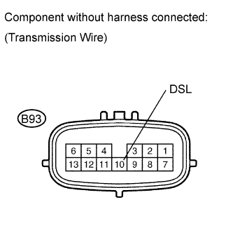
WIRING DIAGRAM
INSPECTION PROCEDURE
- NOTICE:
- Perform the universal trip to clear permanent DTCs (COROLLA_ZRE142 RM000000W770S6X.html).
| 1.INSPECT TRANSMISSION WIRE (DSL) |
Disconnect the transmission wire connector from the transaxle.
Measure the resistance according to the value(s) in the table below.
- Standard resistance:
Tester Connection
| Condition
| Specified Condition
|
10 (DSL) - Body ground
| 20°C (68°F)
| 11 to 13 Ω
|
| 2.CHECK HARNESS AND CONNECTOR (TRANSMISSION WIRE - ECM) |
Connect the transmission wire connector.
Disconnect the ECM connector.
Measure the resistance according to the value(s) in the table below.
- Standard resistance:
Tester Connection
| Condition
| Specified Condition
|
B31-79 (DSL) - Body ground
| 20°C (68°F)
| 11 to 13 Ω
|
| | REPAIR OR REPLACE HARNESS OR CONNECTOR |
|
|
| 3.INSPECT SHIFT SOLENOID VALVE DSL |
Remove the shift solenoid valve DSL.
Measure the resistance according to the value(s) in the table below.
- Standard resistance:
Tester Connection
| Condition
| Specified Condition
|
Solenoid Connector (DSL) - Solenoid Body (DSL)
| 20°C (68°F)
| 11 to 13 Ω
|
Connect the positive (+) lead to the terminal of the solenoid connector, and the negative (-) lead to the solenoid body.
- OK:
- The solenoid valve makes an operating sound.