Anti-Lock Brake System Abs Warning Light Remains On
Brake. Camry. Acv40 Gsv40
DESCRIPTION
WIRING DIAGRAM
INSPECTION PROCEDURE
INSPECT CAN COMMUNICATION SYSTEM
CHECK SKID CONTROL ECU CONNECTOR SECURELY CONNECTED
CHECK BATTERY
INSPECT SKID CONTROL ECU CONNECTOR (IG1 TERMINAL VOLTAGE)
INSPECT SKID CONTROL ECU CONNECTOR (GND TERMINAL CONTINUITY)
INSPECT COMBINATION METER ASSEMBLY
ANTI-LOCK BRAKE SYSTEM - ABS Warning Light Remains ON |
DESCRIPTION
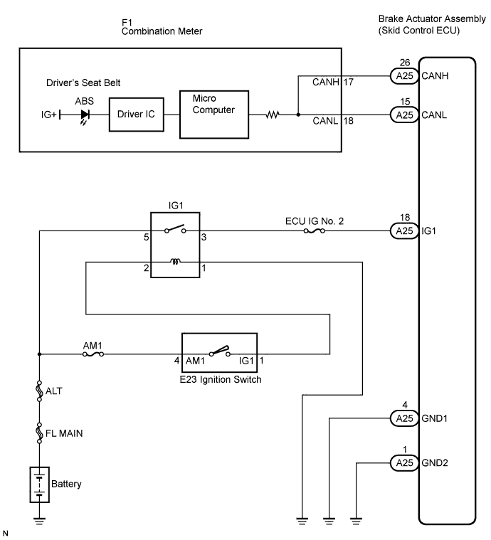
The skid control ECU sends the indicator signals to the combination meter assembly via the CAN communication system.If any of the following is detected, the ABS warning light remains on.- The skid control ECU connectors are disconnected from the skid control ECU.
- There is a malfunction in the skid control ECU internal circuit.
- There is an open in the wire harness between the combination meter and the skid control ECU.
- The ABS and/or EBD is defective.
- HINT:
- The intelligent tester may not be used when the skid control ECU is abnormal.
WIRING DIAGRAM
INSPECTION PROCEDURE
- HINT:
- Check the condition of each related circuit before troubleshooting (CAMRY_ACV40 RM000000UZ301ZX.html).
| 1.INSPECT CAN COMMUNICATION SYSTEM |
Check if a CAN communication system DTC is output (CAMRY_ACV40 RM000001JB800LX.html).
- Result:
Condition
| Proceed to
|
CAN communication system DTC is not output
| A
|
CAN communication system DTC is output
| B
|
| 2.CHECK SKID CONTROL ECU CONNECTOR SECURELY CONNECTED |
Check if the skid control ECU connector is connected.
- OK:
- The connector is securely connected.
| | CONNECT CONNECTOR TO ECU CORRECTLY |
|
|
Check the battery voltage.
- Standard voltage:
- 11 to 14 V
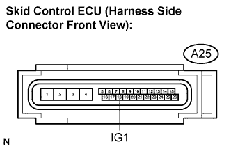
| 4.INSPECT SKID CONTROL ECU CONNECTOR (IG1 TERMINAL VOLTAGE) |
Disconnect the skid control ECU connector.
Turn the ignition switch to the ON position.
Measure the voltage according to the value(s) in the table below.
- Standard voltage:
Tester Connection
| Condition
| Specified Condition
|
A25-18 (IG1) - Body ground
| Ignition switch on
| 10 to 14 V
|
| | REPAIR OR REPLACE HARNESS OR CONNECTOR (IG1 CIRCUIT) |
|
|
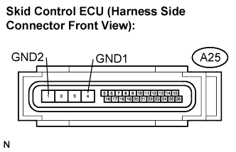
| 5.INSPECT SKID CONTROL ECU CONNECTOR (GND TERMINAL CONTINUITY) |
Measure the resistance according to the value(s) in the table below.
- Standard resistance:
Tester Connection
| Specified Condition
|
A25-4 (GND1) - Body ground
| Below 1 Ω
|
A25-1 (GND2) - Body ground
| Below 1 Ω
|
Connect the connector.
| | REPAIR OR REPLACE HARNESS OR CONNECTOR (GND CIRCUIT) |
|
|
| 6.INSPECT COMBINATION METER ASSEMBLY |
Connect the intelligent tester to the DLC3.
Select the "Active Test" on the tester (CAMRY_ACV40 RM000001JBA003X.html).
Active Test: ABSTester Display
| Test Part/Control Range
| Diagnostic Note
|
ABS Warning Lamp
| Turn ABS warning light ON / OFF
| Observe combination meter
|
Check the ABS warning light operation.
- OK:
- The ABS warning light turns on or off in accordance with the intelligent tester.
- Result:
Condition
| Proceed to
|
OK
| A
|
OK (When troubleshooting in accordance with the PROBLEM SYMPTOMS TABLE)
| B
|
NG
| C
|