Dtc C0210/33 Right Rear Wheel Speed Sensor Signal Malfunction
Brake. Camry. Acv40 Gsv40
DESCRIPTION
WIRING DIAGRAM
INSPECTION PROCEDURE
READ VALUE USING INTELLIGENT TESTER (REAR SPEED SENSOR)
PERFORM TEST MODE INSPECTION (SIGNAL CHECK)
INSPECT SPEED SENSOR SIGNAL WAVEFORM
RECONFIRM DTC
INSPECT SPEED SENSOR INSTALLATION
INSPECT REAR SPEED SENSOR
CHECK HARNESS AND CONNECTOR (SKID CONTROL SENSOR WIRE TO SKID CONTROL ECU)
CHECK HARNESS AND CONNECTOR (SKID CONTROL SENSOR WIRE TO REAR SPEED SENSOR)
INSPECT SPEED SENSOR SIGNAL WAVEFORM
READ VALUE USING INTELLIGENT TESTER (REAR SPEED SENSOR)
RECONFIRM DTC
INSPECT SPEED SENSOR ROTOR
DTC C0210/33 Right Rear Wheel Speed Sensor Signal Malfunction |
DTC C0215/34 Left Rear Wheel Speed Sensor Signal Malfunction |
DTC C1273/73 Low Output Signal of Rear Speed Sensor RH (Test Mode DTC) |
DTC C1274/74 Low Output Signal of Rear Speed Sensor LH (Test Mode DTC) |
DTC C1277/77 Abnormal Change in Output Signal of Rear Speed Sensor RH (Test Mode DTC) |
DTC C1278/78 Abnormal Change in Output Signal of Rear Speed Sensor LH (Test Mode DTC) |
DTC C1332/38 Right Rear Speed Sensor Circuit |
DTC C1333/39 Left Rear Speed Sensor Circuit |
DESCRIPTION
Refer to DTCs C0200/31, C0205/32, C1330/35, and C1331/36 (Link).DTCs from C1273/73 to C1278/78 can be deleted when the speed sensor sends a vehicle speed signal or the test mode ends. DTCs from C1273/73 to C1278/78 are output only in the test mode.DTC No.
| DTC Detecting Condition
| Trouble Area
|
C0210/33
C0215/34
| When either of the following is detected:
- Vehicle speed is more than 40 km/h (25 mph), and pulses are not input for 0.03 sec.
- When the vehicle speed has reached 12 km/h (8 mph), after the initial start or restart a wheel speed of 0 km/h (0 mph) is detected.
| - Rear speed sensor RH and/or LH
- Rear speed sensor circuit RH and/or LH
- Rear speed sensor rotor RH and/or LH
- Sensor installation
- Brake actuator assembly (skid control ECU)
|
C1332/38
C1333/39
| Abnormality in the resistance value of each speed sensor is detected.
| - Rear speed sensor RH and/or LH
- Rear speed sensor circuit RH and/or LH
- Sensor installation
|
C1273/73
C1274/74
| Detected only during test mode.
| - Rear speed sensor
- Sensor installation
- Sensor rotor
|
C1277/77
C1278/78
| Detected only during test mode.
| - Rear speed sensor
- Sensor installation
- Sensor rotor
|
- HINT:
- DTC No. C0210/33 and C1332/38 are for the rear speed sensor RH.
- DTC No. C0215/34 and C1333/39 are for the rear speed sensor LH.
WIRING DIAGRAM
INSPECTION PROCEDURE
- HINT:
- Check the condition of each related circuit connector before troubleshooting (CAMRY_ACV40 RM000000UZ301ZX.html).
| 1.READ VALUE USING INTELLIGENT TESTER (REAR SPEED SENSOR) |
Connect the intelligent tester to the DLC3.
Start the engine.
Select "Data List" and read the value displayed on the intelligent tester (CAMRY_ACV40 RM000001JBA003X.html).
Data List: ABSTester Display
| Measurement Item/Range
| Normal Condition
|
RR Wheel Speed
| Wheel speed sensor (RR) reading / min.: 0 km/h (0 mph), max.: 326 km/h (202 mph)
| Actual wheel speed
|
RL Wheel Speed
| Wheel speed sensor (RL) reading / min.: 0 km/h (0 mph), max.: 326 km/h (202 mph)
| Actual wheel speed
|
Check that there is no difference between the speed value output from the speed sensor displayed on the intelligent tester and the speed value displayed on the speedometer when driving the vehicle.
- OK:
- The speed value output from the speed sensor displayed on the intelligent tester is the same as the actual vehicle speed.
| 2.PERFORM TEST MODE INSPECTION (SIGNAL CHECK) |
Check if test mode (signal check) DTCs are detected (CAMRY_ACV40 RM000001JBD03HX.html).
- Result:
Condition
| Proceed to
|
Test mode (signal check) DTC is not output
| A
|
Test mode (signal check) DTC is output
| B
|
| 3.INSPECT SPEED SENSOR SIGNAL WAVEFORM |
Lift up the vehicle.
Perform the inspection using an oscilloscope.
Disconnect the skid control ECU connector.
Connect the oscilloscope to terminals of the skid control ECU.
Check that a waveform is output when the tires are rotated.
- OK:
- The same waveform is output from rear wheels and there is no noise or interference in the waveform.
- HINT:
- As vehicle speed (wheel rotation speed) increases, the width of the waveform narrows and the output voltage becomes greater.
- When noise is identified in the waveform on the oscilloscope, the erratic signals are generated due to rotor scratches, looseness or foreign matter attached to the speed sensor.
Connect the connector.
| | CLEAN OR REPLACE SPEED SENSOR AND SENSOR ROTOR |
|
|
Clear the DTCs (CAMRY_ACV40 RM000001JB800PX.html).
Drive the vehicle at a speed of approximately 40 km/h (25 mph) or more for 60 seconds or more.
Check if the same DTCs are recorded (CAMRY_ACV40 RM000001JB800PX.html).
- HINT:
- Reinstall the sensors, connectors, etc. and restore the vehicle to its prior condition before rechecking for DTCs.
- Result:
Condition
| Proceed to
|
DTCs (C0210/33, C0215/34, C1332/38 and C1333/39) are output
| A
|
DTCs (C0210/33, C0215/34, C1332/38 and C1333/39) are output (When troubleshooting in accordance with the PROBLEM SYMPTOMS TABLE)
| B
|
DTCs (C0210/33, C0215/34, C1332/38 and C1333/39) are not output (When troubleshooting in accordance with the DTC CHART)
| C
|
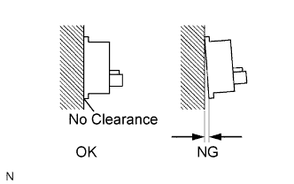
| 5.INSPECT SPEED SENSOR INSTALLATION |
Check the rear speed sensor installation.
- OK:
- There is no clearance between the sensor and rear axle carrier.
- NOTICE:
- Check the speed sensor signal after replacement (CAMRY_ACV40 RM000001JBD03HX.html).
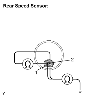
| 6.INSPECT REAR SPEED SENSOR |
Disconnect the rear speed sensor connector.
Measure the resistance according to the value(s) in the table below.
- Standard resistance:
- LH:
Tester Connection
| Specified Condition
|
g1-1 (RL+) - g1-2 (RL-)
| Below 2.2 kΩ
|
g1-1 (RL+) - Body ground
| 10 kΩ or higher
|
g1-2 (RL-) - Body ground
| 10 kΩ or higher
|
- RH:
Tester Connection
| Specified Condition
|
f1-1 (RR+) - f1-2 (RR-)
| Below 2.2 kΩ
|
f1-1 (RR+) - Body ground
| 10 kΩ or higher
|
f1-2 (RR-) - Body ground
| 10 kΩ or higher
|
- NOTICE:
- Check the speed sensor signal after replacement (CAMRY_ACV40 RM000001JBD03HX.html).
| 7.CHECK HARNESS AND CONNECTOR (SKID CONTROL SENSOR WIRE TO SKID CONTROL ECU) |
Check harness and connector.
Disconnect the skid control ECU connector.
Disconnect the skid control sensor wire.
Measure the resistance according to the value(s) in the table below.
- Standard resistance:
- LH:
Tester Connection
| Specified Condition
|
A25-7 (RL+) - g1-1 (RL+)
| Below 1 Ω
|
A25-17 (RL-) - g1-2 (RL-)
| Below 1 Ω
|
g1-1 (RL+) - Body ground
| 10 kΩ or higher
|
g1-2 (RL-) - Body ground
| 10 kΩ or higher
|
- RH:
Tester Connection
| Specified Condition
|
A25-19 (RR+) - f1-1 (RR+)
| Below 1 Ω
|
A25-8 (RR-) - f1-2 (RR-)
| Below 1 Ω
|
f1-1 (RR+) - Body ground
| 10 kΩ or higher
|
f1-2 (RR-) - Body ground
| 10 kΩ or higher
|
| | REPAIR OR REPLACE HARNESS OR CONNECTOR (SKID CONTROL ECU TO SKID CONTROL SENSOR WIRE) |
|
|
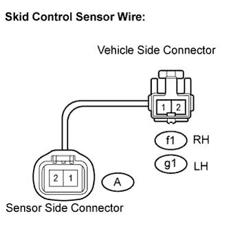
| 8.CHECK HARNESS AND CONNECTOR (SKID CONTROL SENSOR WIRE TO REAR SPEED SENSOR) |
Check harness and connector (skid control sensor wire).
Measure the resistance according to the value(s) in the table below.
- Standard resistance:
- LH:
Tester Connection
| Specified Condition
|
g1-1 - A-1
| Below 1 Ω
|
g1-1 - A-2
| 10 kΩ or higher
|
g1-1 - Body ground
| 10 kΩ or higher
|
g1-2 - A-2
| Below 1 Ω
|
g1-2 - A-1
| 10 kΩ or higher
|
g1-2 - Body ground
| 10 kΩ or higher
|
- RH:
Tester Connection
| Specified Condition
|
f1-1 - A-1
| Below 1 Ω
|
f1-1 - A-2
| 10 kΩ or higher
|
f1-1 - Body ground
| 10 kΩ or higher
|
f1-2 - A-2
| Below 1 Ω
|
f1-2 - A-1
| 10 kΩ or higher
|
f1-2 - Body ground
| 10 kΩ or higher
|
| | REPAIR OR REPLACE SKID CONTROL SENSOR WIRE |
|
|
| 9.INSPECT SPEED SENSOR SIGNAL WAVEFORM |
Lift up the vehicle.
Perform the inspection using the oscilloscope.
Disconnect the skid control ECU connector.
Connect the oscilloscope to terminals of the skid control ECU.
Check that a waveform is output when the tires are rotated.
- OK:
- The same waveforms is output from rear wheels and there is no noise or interference in the waveform.
- HINT:
- As vehicle speed (wheel rotation speed) increases, the width of the waveform narrows and the output voltage becomes greater.
- When noise is identified in the waveform on the oscilloscope, the erratic signals are generated due to rotor scratches, looseness or foreign matter attached to the speed sensor.
Connect the connectors.
| | CLEAN OR REPLACE SPEED SENSOR AND SENSOR ROTOR |
|
|
| 10.READ VALUE USING INTELLIGENT TESTER (REAR SPEED SENSOR) |
Connect the intelligent tester to the DLC3.
Start the engine.
Select "Data List" and read the value displayed on the intelligent tester (CAMRY_ACV40 RM000001JBA003X.html).
Data List: ABSTester Display
| Measurement Item/Range
| Normal Condition
|
RR Wheel Speed
| Wheel speed sensor (RR) reading / min.: 0 km/h (0 mph), max.: 326 km/h (202 mph)
| Actual wheel speed
|
RL Wheel Speed
| Wheel speed sensor (RL) reading / min.: 0 km/h (0 mph), max.: 326 km/h (202 mph)
| Actual wheel speed
|
Check that there is no difference between the speed value output from the speed sensor displayed on the intelligent tester and the speed value displayed on the speedometer when driving the vehicle.
- OK:
- The speed value output from the speed sensor displayed on the intelligent tester is the same as the actual vehicle speed.
- HINT:
- It is suspected that the DTCs were output due to a bad connection of the connector terminal.
- If troubleshooting has been carried out according to the "PROBLEM SYMPTOMS TABLE", refer back to the table and proceed to the next step (CAMRY_ACV40 RM000001JB500OX.html).
Clear the DTCs (CAMRY_ACV40 RM000001JB800PX.html).
Drive the vehicle at a speed of approximately 40 km/h (25 mph) or more for 60 seconds or more.
Check if the same DTCs are recorded (CAMRY_ACV40 RM000001JB800PX.html).
- HINT:
- Reinstall the sensors, connectors, etc. and restore the vehicle to its prior condition before rechecking for DTCs.
- Result:
Condition
| Proceed to
|
DTCs (C0210/33, C0215/34, C1332/38 and C1333/39) are output
| A
|
DTCs (C0210/33, C0215/34, C1332/38 and C1333/39) are not output
| B
|
| 12.INSPECT SPEED SENSOR ROTOR |
Turn the ignition switch off.
Remove the rear axle (CAMRY_ACV40 RM000001IXL002X.html).
Check the rotor.
- OK:
- No scratches, cracks, oil, or foreign matter on the rotors.
- NOTICE:
- Check the speed sensor signal after cleaning or replacement (CAMRY_ACV40 RM000001JBD03HX.html).
Install the rear axle (CAMRY_ACV40 RM000001IXJ014X.html).
| | CLEAN OR REPLACE SPEED SENSOR ROTOR |
|
|