Rear View Monitor System (W/ Navigation System) Park / Neutral Position Switch Circuit
DESCRIPTION
WIRING DIAGRAM
INSPECTION PROCEDURE
CHECK NAVIGATION SYSTEM TYPE
CHECK VEHICLE SIGNAL (DISPLAY CHECK MODE)
CHECK VEHICLE SIGNAL (DISPLAY CHECK MODE)
CHECK NAVIGATION RECEIVER ASSEMBLY
CHECK HARNESS AND CONNECTOR (NAVIGATION RECEIVER ASSEMBLY - PARK/NEUTRAL POSITION SWITCH)
REAR VIEW MONITOR SYSTEM (w/ Navigation System) - Park / Neutral Position Switch Circuit |
DESCRIPTION
The navigation receiver assembly receives a reverse signal from park/neutral position switch.
WIRING DIAGRAM
INSPECTION PROCEDURE
| 1.CHECK NAVIGATION SYSTEM TYPE |
Check the navigation system type.
ResultResult
| Proceed to
|
for HDD Navigation System
| A
|
for DVD Navigation System
| B
|
| 2.CHECK VEHICLE SIGNAL (DISPLAY CHECK MODE) |
Enter the "Failure Check/Setting" mode and select "Vehicle Signal" (RAV4_ACA30 RM000003A3N00MX.html).
Check that the display changes between ON and OFF according to the shift lever operation.
- OK:
Shift Lever Position
| Display
|
R
| ON
|
Except R
| OFF
|
- HINT:
- This display is updated once per second. As a result, it is normal for the display to lag behind the actual change in the switch.
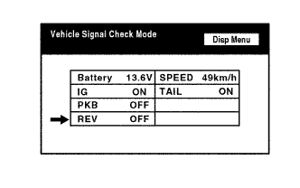
| 3.CHECK VEHICLE SIGNAL (DISPLAY CHECK MODE) |
Enter the "Display Check" mode and select "Vehicle Signal Check Mode" (RAV4_ACA30 RM000003A3N00LX.html).
Check that the display changes between ON and OFF according to the shift lever operation.
- OK:
Shift Lever Position
| Display
|
R
| ON
|
Except R
| OFF
|
- HINT:
- This display is updated once per second. As a result, it is normal for the display to lag behind the actual shift lever operation.
| 4.CHECK NAVIGATION RECEIVER ASSEMBLY |
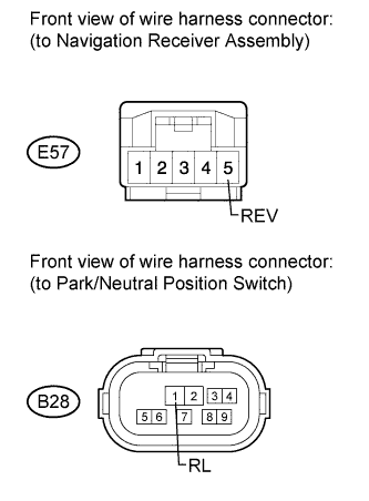
Disconnect the E57 navigation receiver assembly connector.
Measure the voltage according to the value(s) in the table below.
- Standard Voltage:
Tester Connection
| Switch Condition
| Specified Condition
|
E57-5 (REV) - Body ground
| Ignition switch ON, shift lever in R
| 11 to 14 V
|
E57-5 (REV) - Body ground
| Ignition switch ON, shift lever in not R
| Below 1 V
|
ResultResult
| Proceed to
|
OK (for HDD Navigation System)
| A
|
OK (for DVD Navigation System)
| B
|
NG
| C
|
| 5.CHECK HARNESS AND CONNECTOR (NAVIGATION RECEIVER ASSEMBLY - PARK/NEUTRAL POSITION SWITCH) |
for 3ZR-FAE:
Disconnect the E57 navigation receiver assembly connector.
Disconnect the B28 park/neutral position switch connector.
Measure the resistance the according to the value(s) in the table below.
- Standard Resistance:
Tester Connection
| Condition
| Specified Condition
|
E57-5 (REV) - B28-2 (RL)
| Always
| Below 1 Ω
|
E57-5 (REV) - Body ground
| Always
| 10 kΩ or higher
|
except 3ZR-FAE:
Disconnect the E57 navigation receiver assembly connector.
Disconnect the B28 park/neutral position switch connector.
Measure the resistance the according to the value(s) in the table below.
- Standard Resistance:
Tester Connection
| Condition
| Specified Condition
|
E57-5 (REV) - B28-1 (RL)
| Always
| Below 1 Ω
|
E57-5 (REV) - Body ground
| Always
| 10 kΩ or higher
|
ResultResult
| Proceed to
|
OK (for K111)
| A
|
OK (for U140F)
| B
|
NG
| C
|
| |
|
| | REPAIR OR REPLACE HARNESS OR CONNECTOR |
|
|