INSTALL NAVIGATION RECEIVER ASSEMBLY WITH BRACKET (w/ Navigation System)
INSTALL RADIO RECEIVER ASSEMBLY WITH BRACKET (w/ Radio Receiver)
Radio Antenna Cord -- Installation |
| 1. INSTALL NO. 3 ANTENNA CORD SUB-ASSEMBLY |
for Short Body (w/o Sliding Roof):
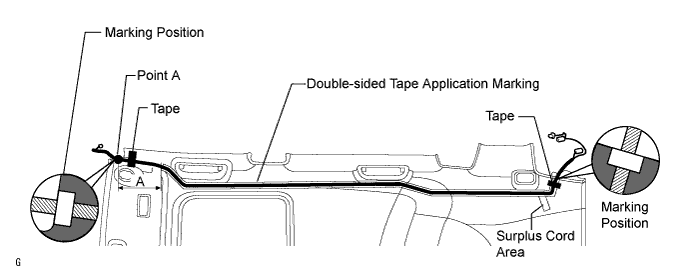
Apply new double-sided tape as shown in the illustration.

- HINT:
- There are no installation markings in area A in the illustration. Therefore, apply the double-sided tape toward point A.
Align the antenna cord masking tape and the edge of the roof headlining. Attach the antenna cord along the double-sided tape.
- HINT:
- Place any extra antenna cord length in the surplus cord area shown in the illustration.
Apply tape to both ends of the antenna cord to fix the cord in place.
for Short Body (w/ Sliding Roof):
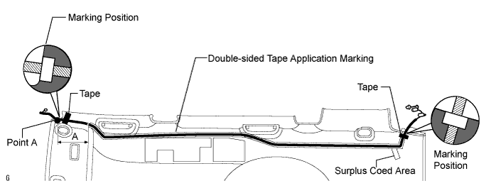
Apply new double-sided tape as shown in the illustration.
- HINT:
- There are no installation markings in area A in the illustration. Therefore, apply the double-sided tape toward point A.
Align the antenna cord masking tape and the edge of the roof headlining. Attach the antenna cord along the double-sided tape.
- HINT:
- Place any extra antenna cord length in the surplus cord area shown in the illustration.
Apply tape to both ends of the antenna cord to fix the cord in place.
for Long Body (w/o Sliding Roof):
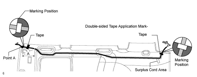
Apply new double-sided tape as shown in the illustration.
- HINT:
- There are no installation markings in area A in the illustration. Therefore, apply the double-sided tape toward point A.
Align the antenna cord masking tape and the edge of the roof headlining. Attach the antenna cord along the double-sided tape.
- HINT:
- Place any extra antenna cord length in the surplus cord area shown in the illustration.
Apply tape to both ends of the antenna cord to fix the cord in place.
for Long Body (w/ Sliding Roof):
Apply new double-sided tape as shown in the illustration.
- HINT:
- There are no installation markings in area A in the illustration. Therefore, apply the double-sided tape toward point A.
Align the antenna cord masking tape and the edge of the roof headlining. Attach the antenna cord along the double-sided tape.
- HINT:
- Place any extra antenna cord length in the surplus cord area shown in the illustration.
Apply tape to both ends of the antenna cord to fix the cord in place.
| 2. INSTALL ROOF HEADLINING ASSEMBLY |
for Short Body:
Install the roof headlining (RAV4_ACA30 RM000001XUR003X.html).
for Long Body:
Install the roof headlining (RAV4_ACA30 RM000001XUX003X.html).
| 3. INSTALL ANTENNA CORD SUB-ASSEMBLY |
for 3ZR-FAE (w/Radio Receiver):
Install the antenna cord with the 4 clamps.
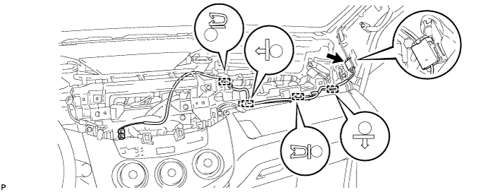
Connect the connector.
except 3ZR-FAE & for 3ZR-FAE (w/o Radio Receiver):
Install the antenna cord with the 4 clamps.
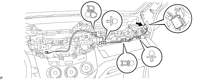
Connect the connector.
| 4. INSTALL UPPER INSTRUMENT PANEL |
Attach the 6 clips and 5 claws to install the instrument panel.
Connect the connector and attach the clamp.
Install the 2 bolts and 2 screws.
Connect the passenger airbag connector.
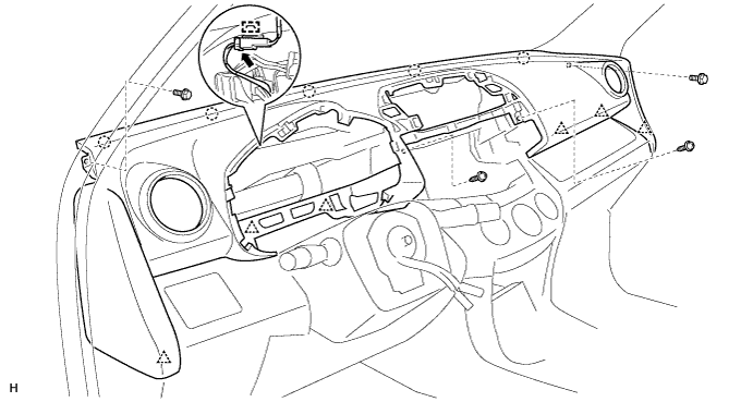
Install the 2 bolts to the passenger airbag.
- Torque:
- 20 N*m{204 kgf*cm, 15 ft.*lbf}
 |
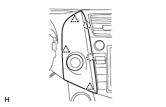
| 5. INSTALL FRONT PILLAR GARNISH LH |
for Short Body:
Install the front pillar garnish (RAV4_ACA30 RM000001XUR003X_01_0039.html).
for Long Body:
Install the front pillar garnish (RAV4_ACA30 RM000001XUX003X_01_0040.html).
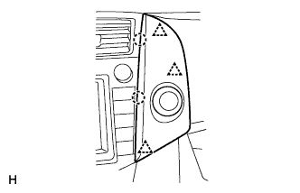
| 6. INSTALL FRONT PILLAR GARNISH RH |
for Short Body:
Install the front pillar garnish (RAV4_ACA30 RM000001XUR003X_01_0048.html).
for Long Body:
Install the front pillar garnish (RAV4_ACA30 RM000001XUX003X_01_0041.html).
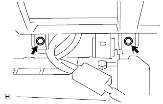
| 7. INSTALL GLOVE COMPARTMENT DOOR ASSEMBLY |
Attach the 2 hinges to install the door.
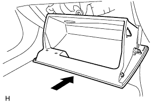 |
Attach the claw to the glove compartment door stopper.
 |
While pushing in the sides of the glove compartment door in the direction indicated by the arrows in the illustration, close the door to engage it to the 2 stoppers.
| 8. INSTALL INSTRUMENT PANEL REGISTER ASSEMBLY CENTER |
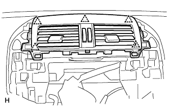 |
Attach the 5 clips to install the instrument panel register.
| 9. INSTALL NAVIGATION RECEIVER ASSEMBLY WITH BRACKET (w/ Navigation System) |
for HDD:
Install the navigation receiver assembly with bracket (RAV4_ACA30 RM0000021Q0003X_01_0001.html).
for DVD:
Install the navigation receiver assembly with bracket (RAV4_ACA30 RM000003P8B001X_01_0003.html).
| 10. INSTALL STEREO OPENING COVER (w/o Radio Receiver) |
|
Attach the 5 clips to install the instrument panel register.
| 11. INSTALL RADIO RECEIVER ASSEMBLY WITH BRACKET (w/ Radio Receiver) |
Remove the radio receiver assembly with bracket. (RAV4_ACA30 RM0000011Q300EX.html).
| 12. INSTALL NO. 1 INSTRUMENT CLUSTER FINISH PANEL CENTER |
 |
Connect the connector.
Attach the 3 clips and 2 claws to install the cluster finish panel.
| 13. INSTALL NO. 2 INSTRUMENT CLUSTER FINISH PANEL CENTER |
 |
Connect the connector.
Attach the 3 clips and 2 claws to install the cluster finish panel.
| 14. INSTALL COMBINATION METER ASSEMBLY |
Connect the connector.
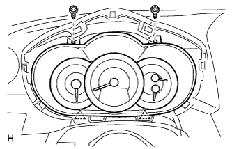 |
Attach the 2 clips to install the combination meter.
Install the 2 screws.
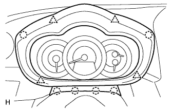
| 15. INSTALL INSTRUMENT CLUSTER FINISH PANEL SUB-ASSEMBLY |
Attach the 4 clips and 6 claws to install the instrument cluster finish panel.
 |
| 16. CONNECT CABLE TO NEGATIVE BATTERY TERMINAL |