Dtc C1249/49 Open In Stop Light Switch Circuit
Brake. Toyota Rav4. Aca30, 33, 38 Gsa33 Zsa30, 35
DESCRIPTION
WIRING DIAGRAM
INSPECTION PROCEDURE
CHECK STOP LIGHT OPERATION
CHECK HARNESS AND CONNECTOR (STP VOLTAGE)
RECONFIRM DTC
INSPECT STOP LIGHT SWITCH ASSEMBLY
DTC C1249/49 Open in Stop Light Switch Circuit |
DESCRIPTION
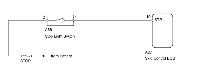
The skid control ECU detects the brake operating conditions through a signal transmitted by the stop light switch. The skid control ECU incorporates an open circuit detection circuit. This DTC is set under either of the following conditions:- An open is detected in the stop light signal input line when the stop light switch is off.
- An open is detected in the stop light circuit lead to the ground when the stop light switch is off.
DTC No.
| DTC Detection Condition
| Trouble Area
|
C1249/49
| When IG1 terminal voltage is 9.5 to 18.5 V, open circuit of stop light switch continues for 3 seconds or more.
| - STOP fuse
- Stop light switch
- Stop light switch circuit
- Stop light control relay circuit
- Brake actuator (Skid control ECU)
|
WIRING DIAGRAM
INSPECTION PROCEDURE
- NOTICE:
- Inspect the fuse for circuits related to this system before performing the following inspection procedure.
| 1.CHECK STOP LIGHT OPERATION |
Check that the stop lights come on when the brake pedal is depressed, and go off when the brake pedal is released.
- OK:
Condition
| Illumination Condition
|
Brake pedal depressed
| ON
|
Brake pedal released
| OFF
|
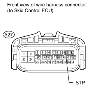
| 2.CHECK HARNESS AND CONNECTOR (STP VOLTAGE) |
Disconnect the A27 ECU connector.
Measure the voltage according to the value(s) in the table below.
- Standard Voltage:
Tester Connection
| Condition
| Specified Condition
|
A27-10 (STP) - Body ground
| Brake pedal depressed
| 8 to 14 V
|
A27-10 (STP) - Body ground
| Brake pedal released
| Below 1.5 V
|
| | REPAIR OR REPLACE HARNESS OR CONNECTOR |
|
|
Clear the DTC (RAV4_ACA30 RM000000ONJ02UX.html).
Check if the same DTC is output (RAV4_ACA30 RM000000ONJ02UX.html).
ResultResult
| Proceed to
|
DTC is output
| A
|
DTC is not output
| B
|
| 4.INSPECT STOP LIGHT SWITCH ASSEMBLY |
Remove the stop light switch (RAV4_ACA30 RM000003P9J002X.html).
Measure the resistance according to the value(s) in the table below.
- Standard Resistance:
Tester Connection
| Switch Condition
| Specified Condition
|
1 - 2
| Pin not pushed
| Below 1 Ω
|
Pin pushed
| 10 kΩ or higher
|
3 - 4
| Pin not pushed
| 10 kΩ or higher
|
Pin pushed
| Below 1 Ω
|