Engine Assembly -- Installation |
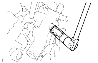
| 1. INSTALL ENGINE COOLANT TEMPERATURE SENSOR |
Using a 19 mm deep socket wrench, install the sensor and a new gasket.
- Torque:
- 20 N*m{204 kgf*cm, 14 ft.*lbf}
 |
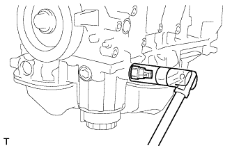
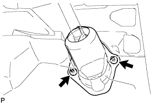
| 2. INSTALL KNOCK SENSOR |
Install the 2 sensors with the 2 bolts as shown in the illustration.
- Torque:
- 20 N*m{205 kgf*cm, 15 ft.*lbf}
- NOTICE:
- Make sure that the knock sensor is in the correct position.
 |
Connect the 2 sensor connectors.
| 3. INSTALL ENGINE OIL PRESSURE SWITCH ASSEMBLY |
Clean the threads of the oil pressure switch. Apply adhesive to 2 or 3 threads of the oil pressure switch.
- Adhesive:
- Toyota Genuine Adhesive 1344, Three Bond 1344 or equivalent
 |
Using a 24 mm deep socket wrench, install the oil pressure switch.
- Torque:
- 21 N*m{214 kgf*cm, 15 ft.*lbf}
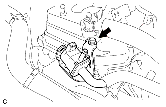
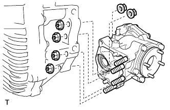
| 4. INSTALL NO. 1 VACUUM SWITCHING VALVE ASSEMBLY |
Install the No. 1 vacuum switching valve with the bolt.
- Torque:
- 10 N*m{102 kgf*cm, 7.4 ft.*lbf}
 |
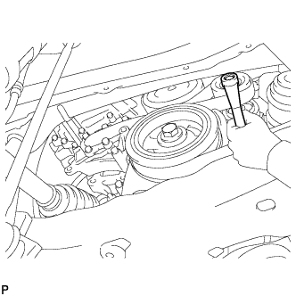
| 5. INSTALL WATER PUMP PULLEY |
Temporarily install the water pump pulley with the 4 bolts.
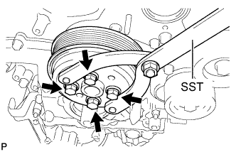 |
Using SST, hold the water pump pulley.
- SST
- 09960-10010(09962-01000,09963-00700)
Tighten the 4 bolts.
- Torque:
- 21 N*m{214 kgf*cm, 15 ft.*lbf}
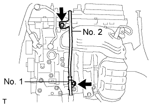
| 6. INSTALL NO. 2 TIMING GEAR COVER |
Install the gear cover with the 2 bolts.
- Torque:
- 6.0 N*m{61 kgf*cm, 53 in.*lbf}
| 7. INSTALL V-RIBBED BELT TENSIONER ASSEMBLY |
Temporarily install the V-ribbed belt tensioner with the 5 bolts.
 |
Install the V-ribbed belt tensioner by tightening the bolt 1 and bolt 2 in the order shown in the illustration.
- Torque:
- 43 N*m{438 kgf*cm, 32 ft.*lbf}
Tighten the other bolts.
- Torque:
- 43 N*m{438 kgf*cm, 32 ft.*lbf}
Each bolt length is as follows: A 70 mm (2.76 in.) B 35 mm (1.37 in.)
| 8. INSTALL DRIVE SHAFT BEARING BRACKET |
Install the drive shaft bearing bracket with the 3 bolts.
- Torque:
- 64 N*m{653 kgf*cm, 47 ft.*lbf}
 |
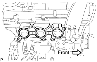
| 9. INSTALL EXHAUST MANIFOLD SUB-ASSEMBLY LH |
Install a new gasket as shown in the illustration.
 |
Install the manifold with the 6 nuts in the order shown in the illustration.
- Torque:
- 21 N*m{214 kgf*cm, 15 ft.*lbf}
 |
| 10. INSTALL NO. 2 EXHAUST MANIFOLD HEAT INSULATOR |
Install the No. 2 heat insulator with the 3 bolts.
- Torque:
- 8.5 N*m{87 kgf*cm, 75 in.*lbf}
| 11. INSTALL NO. 2 MANIFOLD STAY |
Install the No. 2 manifold stay with the bolt and nut in the order shown in the illustration.
- Torque:
- 34 N*m{347 kgf*cm, 25 ft.*lbf}
 |
| 12. INSTALL OIL DIPSTICK GUIDE |
Install 2 new O-rings to the guide.
 |
Apply a light coat of engine oil to the O-rings.
Push in the guide end into the guide hole.
Install the No. 1 guide with the bolt.
- Torque:
- 21 N*m{214 kgf*cm, 15 ft.*lbf}
Install the No. 2 guide with the bolt.
- Torque:
- 21 N*m{214 kgf*cm, 15 ft.*lbf}
Install the dipstick.
| 13. INSTALL GENERATOR ASSEMBLY |
Install the generator with the 2 bolts.
- Torque:
- 43 N*m{438 kgf*cm, 32 ft.*lbf}
 |
Install the bolt to the cylinder block.
- Torque:
- 20 N*m{204 kgf*cm, 15 ft.*lbf}
 |
Connect the generator connector to the generator.
 |
Connect the generator wire with the nut.
- Torque:
- 9.8 N*m{100 kgf*cm, 88 in.*lbf}
Install the terminal cap.
Connect the 2 wire harness clamps.
 |
| 14. INSTALL COOLER COMPRESSOR ASSEMBLY |
Install the cooler compressor with the 4 bolts.
- Torque:
- 24.5 N*m{250 kgf*cm, 18 ft.*lbf}
- NOTICE:
- Tighten the bolts in the order shown in the illustration to install the cooler compressor.
 |
Connect the connector.
| 15. INSTALL NO. 2 IDLER PULLEY SUB-ASSEMBLY |
Install the idler pulley cover plate, idler pulley, No. 2 idler pulley cover plate with the bolt.
- Torque:
- 54 N*m{551 kgf*cm, 40 ft.*lbf}
 |
| 16. INSTALL V-RIBBED BELT |
Rotate the tensioner pulley counterclockwise, and then install the V-ribbed belt.
 |
If it is difficult to install the V-ribbed belt, perform the following procedure.
Put the V-ribbed belt on everything except the tensioner pulley as shown in the illustration.
While releasing the belt tension by turning the belt tensioner counterclockwise, put the V-ribbed belt on the tensioner pulley.
- NOTICE:
- Put the backside of the V-ribbed belt on the tensioner pulley and idler pulley.
- Check that the V-ribbed belt is properly set to each pulley.
 |
| 17. INSTALL EXHAUST MANIFOLD SUB-ASSEMBLY RH |
Install a new gasket as shown in the illustration.
 |
Install the manifold with the 6 nuts in the order shown in the illustration.
- Torque:
- 21 N*m{214 kgf*cm, 15 ft.*lbf}
 |
| 18. INSTALL MANIFOLD STAY |
Install the manifold stay with the 2 bolts and nut in the order shown in the illustration.
- Torque:
- 34 N*m{347 kgf*cm, 25 ft.*lbf}
 |
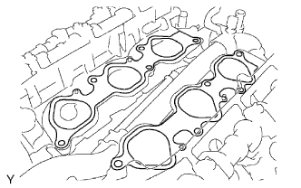
| 19. INSTALL INTAKE MANIFOLD |
Set a new gasket on each cylinder head.
- NOTICE:
- Align the port holes of the gasket and cylinder head.
- Be careful of the installation direction.
 |
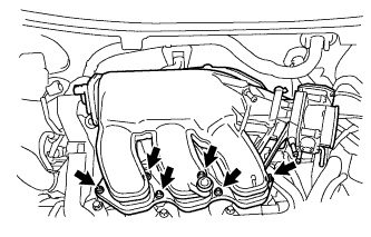
Set the intake manifold on the cylinder heads.
Install and uniformly tighten the 6 bolts and 4 nuts in several passes.
- Torque:
- 21 N*m{214 kgf*cm, 15 ft.*lbf}
 |
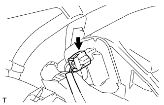
Connect the 6 fuel injector connectors.
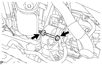
| 20. INSTALL NO. 2 ENGINE MOUNTING STAY RH |
Install the mounting stay with the bolt.
- Torque:
- 21 N*m{214 kgf*cm, 15 ft.*lbf}
| 21. INSTALL IGNITION COIL ASSEMBLY |
Install the 6 ignition coils to the cylinder head with the 6 bolts.
- Torque:
- 10 N*m{102 kgf*cm, 7 ft.*lbf}
| 22. INSTALL INTAKE AIR SURGE TANK ASSEMBLY |
- NOTICE:
- DO NOT apply oil to the bolts listed below: :
Tightening Parts Surge Tank and Intake Manifold No. 1 Surge Tank Stay and Cylinder Head Cover No. 1 Surge Tank Stay and Surge Tank Throttle Body Bracket and Cylinder Head Cover Throttle Body Bracket and Surge Tank
Install a new gasket to the surge tank.
Using a 5 mm hexagon socket wrench, install the 4 bolts and 2 nuts.
- Torque:
- Bolt:
- 18 N*m{184 kgf*cm, 13 ft.*lbf}
- Nut:
- 16 N*m{163 kgf*cm, 12 ft.*lbf}
 |
Install the throttle body bracket and No. 1 surge tank stay with the 4 bolts.
- Torque:
- 21 N*m{214 kgf*cm, 15 ft.*lbf}
Connect the connector.
 |
Connect the No. 1 ventilation hose and vacuum hose.
Install the clamp and connect the throttle body connector.
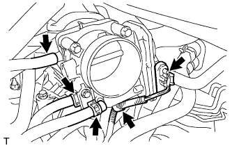 |
Connect the vapor feed hose.
Connect the 2 water by-pass hoses to the throttle body.
| 23. REMOVE ENGINE FROM ENGINE STAND |
Install a sling device and chain block to the engine.
Remove the engine from the engine stand.
| 24. INSTALL DRIVE PLATE AND RING GEAR SUB-ASSEMBLY |
Clean the bolt and its hole.
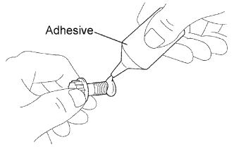 |
Apply adhesive to 2 or 3 threads of the bolt end.
- Adhesive:
- Toyota Genuine Adhesive 1324, Three Bond 1324 or equivalent
Using SST, hold the crankshaft.
- SST
- 09213-70011(09213-70020)
09330-00021
 |
Install the flywheel, drive plate and drive plate spacer on the crankshaft.
Uniformly install and tighten the 8 bolts in the sequence shown in the illustration.
- Torque:
- 83 N*m{847 kgf*cm, 61 ft.*lbf}
- NOTICE:
- Do not start the engine for at least 1 hour after the installation.
 |
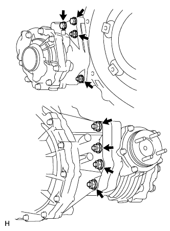
| 25. INSTALL TRANSFER ASSEMBLY |
except K111F:
Install the transfer to the transaxle with the 6 nuts and 2 bolts.- Torque:
- 69 N*m{700 kgf*cm, 51 ft.*lbf}
 |
for K111F:
Install the transfer to the transaxle with the 6 nuts and 2 bolts.- Torque:
- 69 N*m{700 kgf*cm, 51 ft.*lbf}
 |
| 26. INSTALL AUTOMATIC TRANSAXLE ASSEMBLY |
Install the automatic transaxle to the engine with the 7 upper side mounting bolts.
- Torque:
- 64 N*m{653 kgf*cm, 47 ft.*lbf}
- NOTICE:
- Make sure that the 2 knock pins are installed on the engine before installing the transaxle.
 |
Install the 3 lower side mounting bolts.
- Torque:
- Bolt A:
- 37 N*m{377 kgf*cm, 27 ft.*lbf}
- Bolt B:
- 46 N*m{469 kgf*cm, 34 ft.*lbf}
 |
Install the 6 torque converter clutch mounting bolts.
- Torque:
- 41 N*m{418 kgf*cm, 30 ft.*lbf}
- HINT:
- First install the black colored bolt and then the other 5 bolts.
 |
Install the flywheel housing under cover with the 2 bolts.
- Torque:
- 7.8 N*m{80 kgf*cm, 69 in.*lbf}
 |
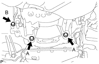
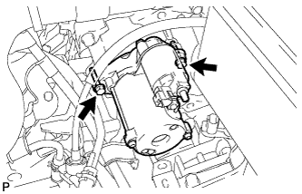
| 27. INSTALL STARTER ASSEMBLY |
Install the starter with the 2 bolts.
- Torque:
- 37 N*m{377 kgf*cm, 27 ft.*lbf}
 |
Connect the starter connector.
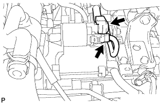 |
Install the terminal nut and cover the nut with the cap.
- Torque:
- 9.8 N*m{100 kgf*cm, 88 in.*lbf}
| 28. INSTALL ENGINE WIRE |
Install the engine wire to the engine.
| 29. INSTALL FRONT SUSPENSION CROSSMEMBER SUB-ASSEMBLY |
Attach the engine together with the transaxle to the suspension crossmember and mounting.
Install the bolt which secures the engine mounting bracket to the mounting insulator.
- Torque:
- 95 N*m{969 kgf*cm, 70 ft.*lbf}
 |
| 30. INSTALL FRONT CROSS MEMBER SUB-ASSEMBLY |
Install the bolt and nut which secure the engine mounting bracket to the mounting insulator.
- Torque:
- 145 N*m{1478 kgf*cm, 107 ft.*lbf}
 |
| 31. INSTALL ENGINE WITH TRANSAXLE |
Place the engine on an engine lifter.
- HINT:
- Place the engine on wooden blocks or equivalent so that the engine is level.
Using the chain block, slowly install the engine to the vehicle and the intermediate shaft to the pinion.
- CAUTION:
- Do not raise the engine more than necessary. If the engine is raised excessively, the vehicle may also be lifted up.
- NOTICE:
- Make sure that the engine is clear of all wiring and hoses.
- While raising the engine into the vehicle, do not allow it to contact the vehicle.
- Align the matchmarks on the intermediate shaft and pinion.
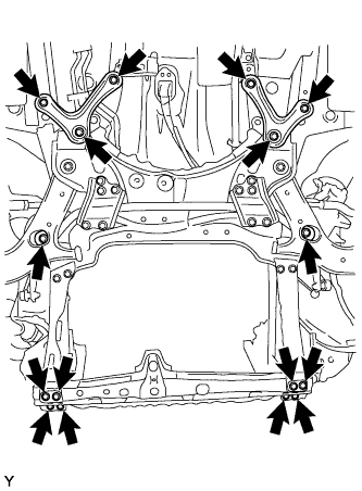
Temporarily install the suspension member and crossmember with the 10 bolts.
 |
Temporarily install the member brace rear RH and LH with the 6 bolts.
Install the engine mounting insulator LH with the bolt and nut.
- Torque:
- 56 N*m{571 kgf*cm, 41 ft.*lbf}
- NOTICE:
- While holding the bolt in place, tighten the nut.
 |
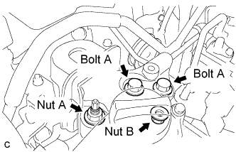
Install the engine mounting insulator RH with the 2 bolts and 2 nuts.
- Torque:
- Bolt and Nut A:
- 95 N*m{969 kgf*cm, 70 ft.*lbf}
- Nut B:
- 52 N*m{530 kgf*cm, 38 ft.*lbf}
 |
Tighten the suspension member and crossmember bolts.
- Torque:
- Bolt A:
- 96 N*m{978 kgf*cm, 71 ft.*lbf}
- Bolt B:
- 137 N*m{1397 kgf*cm, 101 ft.*lbf}
 |
Tighten the member brace rear bolts.
- Torque:
- Bolt C:
- 137 N*m{1397 kgf*cm, 101 ft.*lbf}
- Bolt D:
- 93 N*m{948 kgf*cm, 69 ft.*lbf}
Remove the sling device and chain block.
Remove the 2 bolts and No. 1 and No. 2 engine hangers.
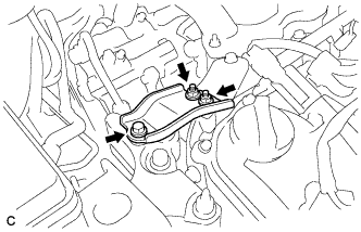
| 32. INSTALL NO. 2 ENGINE MOUNTING STAY RH |
Install the No. 2 engine mounting stay RH with the bolt and 2 nuts.
- Torque:
- 20 N*m{204 kgf*cm, 15 ft.*lbf}
 |
| 33. INSTALL FRONT DRIVE SHAFT LH |
Install the front drive shaft LH (RAV4_ACA30 RM00000226O008X.html).
| 34. INSTALL FRONT DRIVE SHAFT RH |
Install the front drive shaft RH (RAV4_ACA30 RM00000226O008X.html).
| 35. CONNECT TIE ROD END SUB-ASSEMBLY LH |
Screw the lock nut and tie rod end on the rack end until the matchmarks are aligned and temporarily tighten the lock nut.
- HINT:
- Fully tighten the lock nut after adjusting toe-in.
 |
| 36. CONNECT TIE ROD END SUB-ASSEMBLY RH |
- HINT:
- Install the RH side by following the same procedures as for the LH side.
| 37. INSTALL NO. 1 STEERING COLUMN HOLE COVER SUB-ASSEMBLY |
Install the steering column hole cover to the steering gear with a new clamp.
| 38. CONNECT STEERING INTERMEDIATE SHAFT |
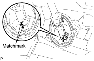 |
Align the matchmarks and install the No. 2 steering intermediate shaft to the steering intermediate shaft.
- Torque:
- 35 N*m{360 kgf*cm, 26 ft.*lbf}
| 39. INSTALL COLUMN HOLE COVER SILENCER SHEET |
 |
Install the silencer sheet with the 2 clips.
Install the floor carpet.
| 40. INSTALL FRONT WHEELS |
| 41. TEMPORARILY INSTALL PROPELLER WITH CENTER BEARING SHAFT ASSEMBLY |
Align the matchmarks of the transfer and propeller shaft.
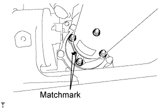 |
Temporarily install the propeller shaft with center bearing with the 4 nuts and 4 washers.
Align the matchmarks of the differential carrier and propeller shaft.
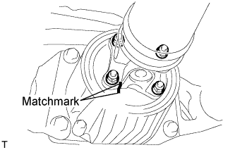 |
Temporarily install the propeller shaft with center bearing with the 4 nuts and 4 washers.
Temporarily install the center support bearing and center support bearing washer with the 2 bolts.
 |
| 42. TIGHTEN PROPELLER WITH CENTER BEARING SHAFT ASSEMBLY |
Tighten the 4 nuts of the propeller shaft and transfer to the torque specification.
- Torque:
- 35 N*m{357 kgf*cm, 26 ft.*lbf}
Tighten the 4 nuts of the propeller shaft and differential carrier to the torque specification.
- Torque:
- 35 N*m{357 kgf*cm, 26 ft.*lbf}
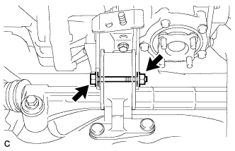
Check that the center line of the center support bearing housing is perpendicular to the axis of the propeller shaft.
Tighten the 2 bolts of the center support bearing to the torque specification.
- Torque:
- 37 N*m{375 kgf*cm, 27 ft.*lbf}
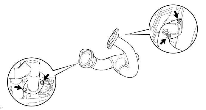
| 43. INSTALL FRONT EXHAUST PIPE ASSEMBLY |
Install a new gasket.
Install the front exhaust pipe assembly with the 2 nuts.

- Torque:
- 62 N*m{632 kgf*cm, 46 ft.*lbf}
| 44. INSTALL NO. 1 FRONT EXHAUST PIPE SUPPORT BRACKET |
Install the No. 1 exhaust pipe support bracket with the 2 bolts.
- Torque:
- 21 N*m{214 kgf*cm, 16 ft.*lbf}
| 45. INSTALL CENTER EXHAUST PIPE ASSEMBLY |
Install 2 new gaskets.
Install the center exhaust pipe assembly with the 2 bolts and 2 nuts.
- Torque:
- 43 N*m{440 kgf*cm, 32 ft.*lbf}
| 46. INSTALL NO. 2 EXHAUST PIPE SUB-ASSEMBLY |
Install the No. 2 exhaust pipe sub-assembly (RAV4_ACA30 RM00000252Q007X.html).
| 47. INSTALL HEATED OXYGEN SENSOR |
Install the heated oxygen sensor (RAV4_ACA30 RM000001RON00QX.html).
| 48. CONNECT TRANSMISSION CONTROL CABLE ASSEMBLY |
Connect the transmission control cable assembly (RAV4_ACA30 RM000001SU600VX.html).
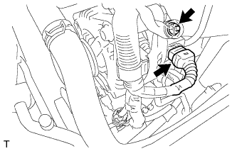
| 49. CONNECT TRANSMISSION OIL COOLER HOSE |
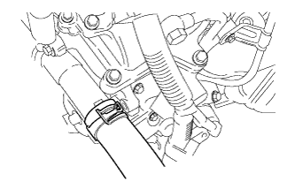
Connect the 2 hoses to the transmission oil filler tube and oil cooler tube.
 |
| 50. CONNECT RADIATOR HOSE INLET |
Install the radiator hose inlet with the clamp.
 |
| 51. CONNECT RADIATOR HOSE OUTLET |
Install the radiator hose outlet with the clamp.
 |
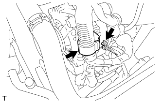
| 52. CONNECT NO. 1 COOLER REFRIGERANT DISCHARGE HOSE |
 |
Remove the attached vinyl tape from the hose.
Sufficiently apply compressor oil to a new O-ring and the fitting surface of the cooler compressor.
- Compressor oil:
- ND-OIL 8 or equivalent
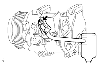
Install the O-ring to the cooler refrigerant discharge hose.
Connect the cooler refrigerant discharge hose to the cooler compressor with the bolt.
- Torque:
- 9.8 N*m{100 kgf*cm, 7 ft.*lbf}
| 53. INSTALL NO. 1 COOLER REFRIGERANT SUCTION HOSE |
 |
Remove the attached vinyl tape from the hose.
Sufficiently apply compressor oil to a new O-ring and the fitting surface of the cooler compressor.
- Compressor oil:
- ND-OIL 8 or equivalent
Install the O-ring to the cooler refrigerant suction hose.
Connect the cooler refrigerant suction hose to the cooler compressor with the bolt.
- Torque:
- 9.8 N*m{100 kgf*cm, 7 ft.*lbf}
| 54. CONNECT UNION TO CHECK VALVE HOSE |
Connect the union to check valve hose.
| 55. INSTALL NO. 1 FUEL VAPOR FEED HOSE |
Install the No. 1 fuel vapor feed hose with the clamp.
 |
| 56. INSTALL RADIATOR RESERVOIR TANK ASSEMBLY |
Install the reservoir tank with the 2 bolts.
- Torque:
- 5.0 N*m{51 kgf*cm, 44 in.*lbf}
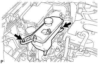 |
Connect the 2 hoses.
| 57. CONNECT HEATER INLET WATER HOSE |
Connect the heater water inlet hose.
 |
| 58. CONNECT HEATER OUTLET WATER HOSE |
Connect the heater water outlet hose.
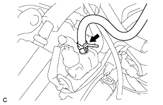
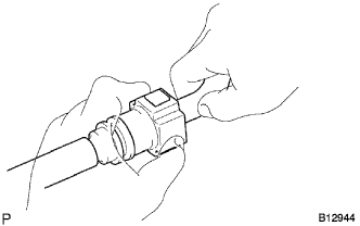
| 59. CONNECT FUEL TUBE SUB-ASSEMBLY |
Push in the fuel tube connector to the fuel pipe until the connector makes a "click" sound.
- NOTICE:
- Check for damage or contamination on the connected part of the pipe.
- Check if the pipe and the connector are securely connected by trying to pull them apart.
 |
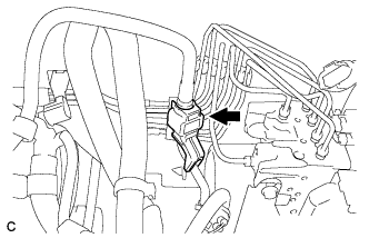
Install the No. 1 fuel pipe clamp.
 |
| 60. CONNECT ENGINE WIRE |
Connect the starter wire with the nut.
- Torque:
- 9.8 N*m{100 kgf*cm, 7 ft.*lbf}
Install the 4 clamps to the body with the bolt.
- Torque:
- 8.4 N*m{86 kgf*cm, 74 in.*lbf}
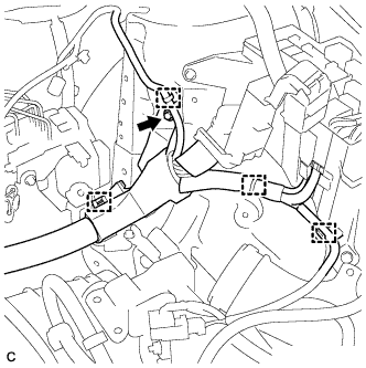 |
Connect the engine wire to the engine room junction block. Then, install it with the 3 connectors and nut.
- Torque:
- 12 N*m{122 kgf*cm, 9 ft.*lbf}
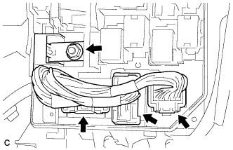 |
Install the engine room junction block cover upper.
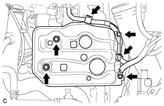
| 61. INSTALL ECM |
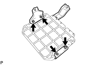
Install the 2 brackets to the ECM with the 4 screws.
- Torque:
- 3.0 N*m{30 kgf*cm, 27 in.*lbf}
 |
Connect the 2 ECM connectors.
- NOTICE:
- When connecting the connector, make sure that dirt, water and other foreign matter does not become stuck between the connector and other part.
Connect the 2 ECM connectors and lower the 2 levers.
- NOTICE:
- Make sure that the 2 levers are securely locked.
 |
Install the ECM with the 3 bolts.
- Torque:
- 6.5 N*m{66 kgf*cm, 57 in.*lbf}
 |
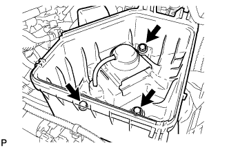
| 62. INSTALL AIR CLEANER CASE |
Install the air cleaner case with the 3 bolts.
- Torque:
- 5.0 N*m{51 kgf*cm, 44 in.*lbf}
 |
Connect the harness clamp.
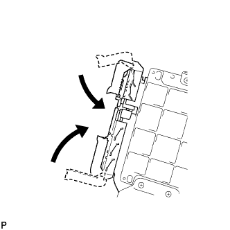
| 63. INSTALL AIR CLEANER CAP SUB-ASSEMBLY |
Install the air cleaner filter element onto the air cleaner case.
Insert the hinge part of the air cleaner cap into the air cleaner case, then hang the 2 hook clamps.
 |
Tighten the No. 1 air cleaner hose clamp.
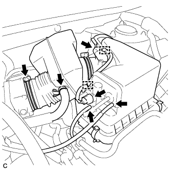 |
Connect the No. 2 ventilation hose to the air cleaner hose.
Connect the 2 wire harness clamps and 2 vacuum hoses.
Connect the VSV (intake air control) connector.
Connect the mass air flow meter connector.
| 64. INSTALL BATTERY BRACKET REINFORCEMENT |
Install the bracket reinforcement with the 2 bolts.
- Torque:
- 19 N*m{194 kgf*cm, 14 ft.*lbf}
 |
| 65. INSTALL FRONT BATTERY BRACKET |
Install the front battery bracket with the 4 bolts.
- Torque:
- 19 N*m{194 kgf*cm, 14 ft.*lbf}
 |
Attach the 2 wire harness clamps.
| 66. INSTALL BATTERY |
Install the battery and battery insulator.
| 67. INSTALL BATTERY CLAMP SUB-ASSEMBLY |
Attach the hook of the battery clamp to the front battery bracket.
Temporarily tighten the nut and install the bolt.
Adjust the battery clamp position.
Fully tighten the nut and bolt.
- Torque:
- Bolt:
- 17 N*m{170 kgf*cm, 12 ft.*lbf}
- Nut:
- 4.9 N*m{50 kgf*cm, 43 in.*lbf}
 |
Attach the 2 wire harness clamps.
| 68. CONNECT CABLE TO NEGATIVE BATTERY TERMINAL |
| 69. INSTALL HOOD SUB-ASSEMBLY |
Install the hood (RAV4_ACA30 RM00000161X00KX.html).
Adjust the hood (RAV4_ACA30 RM00000138K00WX.html).
| 70. ADD TRANSFER OIL |
Remove the case plug (for filler) and gasket.
Pour oil so that the oil level is between 0 to 5.0 mm (0 to 0.197 in.) from the bottom lip of the case plug (for filler) hole.
- NOTICE:
- When adding oil, pour it slowly.
- Add oil a little at a time, waiting several minutes between each addition of oil.
Wait approximately 5 minutes and check that the oil level has not changed.
Install a new gasket and the case plug (for filler).
- Torque:
- 39 N*m{398 kgf*cm, 28 ft.*lbf}
| 71. ADD ENGINE OIL |
Wipe the oil pan and drain plug before installing the plug.
Install a new gasket and the oil pan drain plug.
- Torque:
- 40 N*m{408 kgf*cm, 30 ft.*lbf}
Add clean engine oil and install the oil filler cap.
- Standard Oil Grade:
Oil Grade Oil Viscosity (SAE) API grade SL or SM multigrade engine oil - 15W-40
- 20W-50
API grade SL "Energy-Conserving", SM "Energy-Conserving" or ILSAC multigrade engine oil - 5W-30
- 10W-30
- 15W-40
- Standard oil capacity:
Item Specified Condition Drain and refill with oil filter change 6.1 liters (6.4 US qts, 5.4 Imp. qts) Drain and refill without oil filter change 5.7 liters (6.0 US qts, 5.0 Imp. qts) Dry fill 6.8 liters (7.2 US qts, 6.0 Imp. qts)
| 72. ADD ENGINE COOLANT |
Tighten the radiator drain cock plug by hand.
Tighten the 2 cylinder block drain cock plugs.
- Torque:
- 13 N*m{130 kgf*cm, 10 ft.*lbf}
Add TOYOTA Super Long Life Coolant (SLLC) to the radiator reservoir filler opening.
Continue adding TOYOTA SLLC until it is filled to the B line at the base of the reservoir's filler neck.
- Standard capacity:
- 9.3 liters (9.8 US qts, 8.2 Imp. qts)
- HINT:
- TOYOTA vehicles are filled with TOYOTA SLLC at the factory. In order to avoid damage to the engine cooling system and other technical problems, only use TOYOTA SLLC or similar high quality ethylene glycol based non-silicate, non-amine, non-nitrite, non-borate coolant with long-life hybrid organic acid technology (coolant with long-life hybrid organic acid technology consists of a combination of low phosphates and organic acids).
- NOTICE:
- Never use water as a substitute for engine coolant.
 |
Squeeze the No. 1 and No. 2 radiator hoses several times by hand, and then check the level of the coolant. If the coolant level drops below the B line, add TOYOTA SLLC to the B line.
Install the radiator reservoir cap.
Start the engine and warm it up until the cooling fan operates. While the cooling fan operates, circulate the coolant for several minutes.
Set the air conditioning as follows while warming up the engine.
Item Specified Condition Manual Air Conditioning System Fan speed: Any setting except OFF Temperature: Toward WARM
Air conditioning switch: OFFAutomatic Air Conditioning System Temperature: Toward MAX
Air conditioning switch: OFFMaintain the engine speed at 2,000 to 2,500 rpm and warm up the engine until the cooling fan operates.
- NOTICE:
- Make sure that some coolant remains in the radiator reservoir.
- Pay attention to the needle of the water temperature meter. Make sure that the needle does not show an abnormally high temperature.
- If there is not enough coolant, the engine may burn out or overheat.
- Immediately after starting the engine, if the radiator reservoir does not have any coolant, perform the following: 1) stop the engine, 2) wait until the coolant has cooled down, and 3) add coolant until the coolant is filled to the B line.
- Run the engine at 2,000 rpm until the coolant level has stabilized.
Squeeze the No. 1 and No. 2 radiator hoses several times to bleed air.
- CAUTION:
- When squeezing the radiator hoses:
- Wear protective gloves.
- Be careful as the radiator hoses are hot.
- Keep your hands away from the radiator fan.
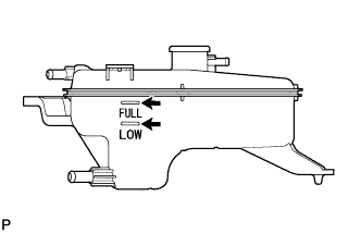
Stop the engine and wait until the coolant cools down to ambient temperature.
Check that the coolant level is between the FULL and LOW lines.
If the coolant level is below the LOW line, repeat all of the procedures above.
If the coolant level is above the FULL line, drain coolant so that the coolant level is between the FULL and LOW lines.
 |
| 73. ADD AUTOMATIC TRANSAXLE FLUID |
- Fluid type:
- Toyota Genuine ATF WS
| 74. CHARGE REFRIGERANT |
Perform vacuum purging using a vacuum pump.
Charge refrigerant HFC-134a (R134a).
- Standard:
- 430 +-30 g (15.2 +-1.1 oz.)
- SST
- 09985-20010(09985-02130,09985-02150,09985-02090,09985-02110,09985-02010,09985-02050,09985-02060,09985-02070)
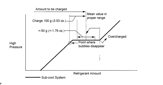
- NOTICE:
- Do not operate the cooler compressor before charging refrigerant as the cooler compressor will not work properly without any refrigerant, and will overheat.
- Approximately 100 g (3.53 oz.) of refrigerant may need to be charged after bubbles disappear. The refrigerant amount should be checked by measuring its quantity, and not with the sight glass.
| 75. INSPECT AUTOMATIC TRANSAXLE FLUID |
- HINT:
- Drive the vehicle so that the engine and transaxle are at normal operating temperature.
- Fluid temperature:
- 70 to 80°C (158 to 176°F)
Park the vehicle on a level surface and apply the parking brake.
With the engine idling and the brake pedal depressed, move the shift lever to each position from the P position to the L position, and return it to the P position.
 |
Pull out the dipstick and wipe it clean.
Push it back fully into the pipe.
Pull it out again and check that the fluid level is within the HOT range. If the fluid level is below the HOT range, add new fluid and recheck the fluid level. If the fluid level exceeds the HOT range, drain the fluid once, add a proper amount of new fluid and recheck the fluid level.
| 76. INSPECT FOR OIL LEAK |
Start the engine. Make sure that no oil leaks from the connections of the oil filter cap.
| 77. INSPECT FOR COOLANT LEAK |
Remove the radiator reservoir cap.
- CAUTION:
- Do not remove the radiator reservoir cap while the engine and radiator are still hot. Pressurized, hot engine coolant and steam may be released and cause serious burns.
Fill the radiator with coolant, and then attach a radiator cap tester.
 |
Warm up the engine.
Pump the radiator cap tester to 118 kPa (1.2 kgf/cm2, 17.1 psi), and then check that the pressure does not drop.
If the pressure drops, check the hoses, radiator and water pump for leakage.
If there are no signs of external coolant leaks, check the heater core, cylinder block and head.
Reinstall the radiator cap.
| 78. INSPECT FOR REFRIGERANT LEAK |
After recharging the refrigerant gas, check for refrigerant gas leakage using a halogen leak detector.
Perform the operation under these conditions:
- Stop the engine.
- Secure good ventilation (the gas leak detector may react to volatile gases other than refrigerant, such as evaporated gasoline or exhaust gas).
- Repeat the test 2 or 3 times.
- Make sure that some refrigerant remains in the refrigeration system. When compressor is off: approximately 392 to 588 kPa (4 to 6 kgf/cm2, 57 to 85 psi)
- Stop the engine.
Using a gas leak detector, check the refrigerant line for leakage.
 |
If a gas leak is not detected on the drain hose, remove the blower motor control (blower resistor) from the cooling unit. Insert the gas leak detector sensor into the unit and perform the test.
Disconnect the connector and leave the pressure switch on for approximately 20 minutes. Bring the gas leak detector close to the pressure switch and perform the test.
| 79. INSPECT FOR FUEL LEAK |
| 80. INSPECT FOR EXHAUST GAS LEAK |
| 81. INSPECT JOINT ANGLE |
- NOTICE:
- Perform the measurement with a 4 post lift or pit so that the vehicle is supported by all 4 wheels as if it were on the ground.
Before the angle measurement, stabilize each part by performing procedures like those described below.
Rotate the propeller shaft several times by hand.
Set the jack to the differential, and raise and lower the differential.
Using SST and a straightedge, measure the angle of the transfer flange (angle D) and the angle of the intermediate shaft (angle A).
- SST
- 09370-50010
- NOTICE:
- Make sure the straightedge and SST are at a right angle.
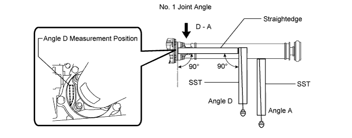
Subtract the measured angle of the intermediate shaft (angle A) from the measured angle of the transfer flange (angle D) to obtain the No. 1 joint angle.
- No. 1 Joint Angle:
Measurement Position No. 1 Joint Angle D - A 2°27' +/-60'
Using SST, measure the angle of the intermediate shaft (angle A) and the angle of the propeller shaft (angle B).
- SST
- 09370-50010
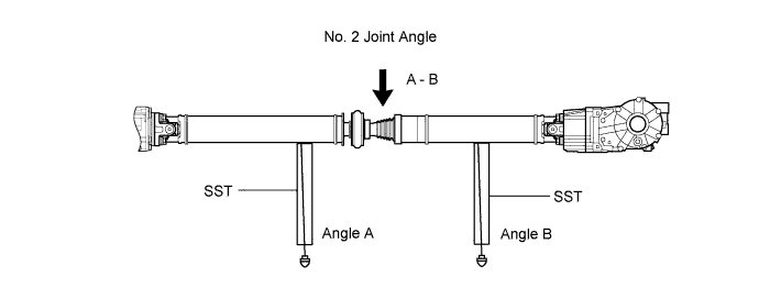
Subtract the measured angle of the propeller shaft (angle B) from the measured angle of the intermediate shaft (angle A) to obtain the No. 2 joint angle.
- No. 2 Joint Angle:
Measurement Position Engine Transmission No. 2 Joint Angle A - B 1AZ-FE A/T 1°29' +/-1°30' M/T 1°28' +/-1°30' 2AZ-FE A/T 1°35' +/-1°30' M/T 1°34' +/-1°30' 2GR-FE A/T 1°35' +/-1°30' 3ZR-FAE M/T 1°28' +/-1°30' CVT 1°29' +/-1°30' 2AD-FTV
2AD-FHVM/T 1°29' +/-1°30'
Using SST, measure the angle of the propeller shaft (angle B) and the angle of the rear differential (angle C).
- SST
- 09370-50010

Subtract the measured angle of the propeller shaft (angle B) from the measured angle of the rear differential (angle C) to obtain the No. 3 joint angle.
- No. 3 Joint Angle:
Measurement Position Engine Transmission No. 3 Joint Angle B - C 1AZ-FE A/T 2°10' +/-60' M/T 2°11' +/-60' 2AZ-FE A/T 2°04' +/-60' M/T 2GR-FE A/T 2°04' +/-60' 3ZR-FAE M/T 2°11' +/-60' CVT 2°11' +/-60' 2AD-FTV
2AD-FHVM/T 2°10' +/-60'
| 82. INSPECT SHIFT LEVER POSITION |
Inspect the shift lever position (RAV4_ACA30 RM000001SU600VX.html).
| 83. ADJUST TRANSMISSION CONTROL CABLE ASSEMBLY |
Adjust the shift lever position (RAV4_ACA30 RM000001SU600VX.html).
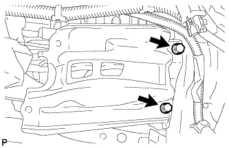
| 84. INSTALL NO. 2 ENGINE UNDER COVER |
Install the under cover with the 2 clips.
| 85. INSTALL REAR ENGINE UNDER COVER LH |
Install the under cover with the 2 clips.
| 86. INSTALL REAR ENGINE UNDER COVER RH |
Install the under cover with the 2 clips.
| 87. INSTALL NO. 1 ENGINE UNDER COVER |
Install the under cover with the 2 bolts, 4 screw and 12 clips.
| 88. ADJUST FRONT WHEEL ALIGNMENT |
Adjust the front wheel alignment (RAV4_ACA30 RM00000227W003X.html).
| 89. INSPECT IGNITION TIMING |
Warm up and stop the engine.
- NOTICE:
- A warmed up engine should have an engine coolant temperature of over 80°C (176°F) and an engine oil temperature of 60°C (140°F), and the engine rpm should be stabilized.
When using the intelligent tester:
Connect the intelligent tester to the DLC3.
Start the engine and idle it.
Turn the intelligent tester main switch on.
Enter the following menus: Powertrain / Engine and ECT / Data List / IGN Advance.
- Standard ignition timing:
- 8 to 12° BTDC at idle
- HINT:
- Refer to the intelligent tester operator's manual for further details.
When not using the intelligent tester:
Remove the V-bank cover (RAV4_ACA30 RM0000019Y9015X_01_0090.html).
Connect the tester terminal of a timing light to the red lead wire as shown in the illustration.
- HINT:
- Use a timing light that detects primary signals.
Using SST, connect terminals 13 (TC) and 4 (CG) of the DLC3.
- SST
- 09843-18040
- NOTICE:
- Confirm the terminal numbers before connecting them. Connecting the wrong terminals can damage the engine.
- When checking the ignition timing, the transmission should be in the neutral position.
Using a timing light, check the ignition timing.
- Standard ignition timing:
- 8 to 12° BTDC at idle
- NOTICE:
- When checking the ignition timing, the transmission should be in the neutral position.
- HINT:
- Run the engine at 1000 to 1300 rpm for 5 seconds, and then check that the engine rpm returns to idle speed.
Remove SST from the DLC3.
Check the ignition timing.
- Standard ignition timing:
- 5 to 15° BTDC at idle
Check that the ignition timing advances immediately when the engine speed is increased.
Disconnect the timing light from the engine.
Install the V-bank cover (RAV4_ACA30 RM0000019Y7015X_01_0114.html).


| 90. INSPECT ENGINE IDLE SPEED |
Warm up and stop the engine.
- NOTICE:
- A warmed up engine should have an engine coolant temperature of over 80°C (176°F) and an engine oil temperature of 60°C (140°F), and the engine rpm should be stabilized.
When using the intelligent tester:
Connect the intelligent tester to the DLC3.
- NOTICE:
- Switch off all accessories and A/C before connecting the intelligent tester.
Race the engine at 2500 rpm for approximately 90 seconds.
Turn the intelligent tester main switch on.
Enter the following menus: Powertrain / Engine and ECT / Data List / Engine Speed.
- Standard idle speed:
- 600 to 700 rpm
- NOTICE:
- When checking the idle speed, the transmission should be in the neutral position.
- HINT:
- Refer to the intelligent tester operator's manual for further details.
Disconnect the intelligent tester from the DLC3.
When not using the intelligent tester:
Using SST, connect the tachometer probe to terminal 9 (TAC) of the DLC3.
- SST
- 09843-18040
- NOTICE:
- Confirm the terminal numbers before connecting them. Connecting the wrong terminals can damage the engine.
Race the engine at 2500 rpm for approximately 90 seconds.
Check the idle speed.
- Standard idle speed:
- 600 to 700 rpm (Transmission in neutral position)
Disconnect the tachometer probe from the DLC3.
 |
| 91. INSPECT CO/HC |
- HINT:
- This check is for determining whether or not the idle CO/HC complies with regulations.
Start the engine.
Keep the engine speed at 2500 rpm for approximately 180 seconds.
Insert a CO/HC meter testing probe at least 40 cm (1.3 ft.) into the tailpipe during idling.
Immediately check the CO/HC concentration at idle and/or 2500 rpm.
- HINT:
- When performing the 2 mode (2500 rpm and idle) test, follow the measurement order prescribed by the applicable local regulations.
- If the CO/HC concentration does not comply with regulations, troubleshoot in the following order.
Check the air fuel ratio sensor and heated oxygen sensor operation.
See the table below for the possible cause, then inspect and correct the applicable causes if necessary.
CO HC Symptom Causes Normal High Rough idle - 1. Faulty ignitions
- Incorrect timing
- Fouled, shorted or improperly gapped plugs
- 2. Leaky intake and exhaust valves
- 3. Leaky cylinder
Low High Rough idle
(Fluctuating HC reading)- 1. Vacuum leaks
- PCV hose
- Intake manifold
- Throttle body
- 2. Lean mixture causing misfire
High High Rough idle
(Black smoke from exhaust)- 1. Restricted air filter
- 2. Faulty fuel SFI system
- Abnormal pressure
- Defective ECT sensor
- Faulty ECM
- Faulty injector
- Faulty throttle position sensor
- Faulty MAF sensor
- 1. Faulty ignitions
| 92. INSTALL V-BANK COVER SUB-ASSEMBLY |
Attach the 3 clips to install the engine cover.
 |
| 93. INSTALL RADIATOR SUPPORT OPENING COVER |
Install the cover with the 9 clips.
 |