DESCRIPTION
WIRING DIAGRAM
INSPECTION PROCEDURE
CHECK HARNESS AND CONNECTOR (MOMENTARY INTERRUPTION)
READ VALUE USING INTELLIGENT TESTER (RR/RL WHEEL SPEED)
PERFORM TEST MODE (SIGNAL CHECK)
RECONFIRM DTC
CHECK IF SKID CONTROL ECU AND REAR SPEED SENSOR CONNECTORS ARE SECURELY CONNECTED
RECONFIRM DTC
CHECK REAR SPEED SENSOR INSTALLATION
CHECK REAR SPEED SENSOR TIP
INSPECT REAR SPEED SENSOR
CHECK HARNESS AND CONNECTOR (SKID CONTROL ECU - REAR SPEED SENSOR)
INSPECT SKID CONTROL ECU (SENSOR INPUT)
REPLACE REAR SPEED SENSOR
RECONFIRM DTC
REPLACE REAR SKID CONTROL ROTOR
RECONFIRM DTC
DTC C0210/33 Rear Speed Sensor RH Circuit |
DTC C0215/34 Rear Speed Sensor LH Circuit |
DTC C1273/73 Low Output Signal of Rear Speed Sensor RH (Test Mode DTC) |
DTC C1274/74 Low Output Signal of Rear Speed Sensor LH (Test Mode DTC) |
DESCRIPTION
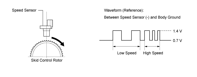
The speed sensors detect the wheel speeds and send appropriate signals to the skid control ECU. The speed sensor has a magnet behind its detection terminal, and detects changes in magnetic flux density between the peaks and valleys of the magnetic rotor teeth.The speed sensors detect those magnetic changes and send pulse signals to the skid control ECU. The ECU monitors the wheel speeds through these pulse signals to control the ABS.DTCs C1273/73 and C1274/74 are deleted when the speed sensor sends a vehicle speed signal or Test Mode ends. DTCs C1273/73 and C1274/74 are output only in Test Mode.- HINT:
- When the connectors between the speed sensor and skid control ECU are connected, the following waveform is output.
DTC Code
| DTC Detection Condition
| Trouble Area
|
C0210/33
C0215/34
| When one of the following conditions is met:
- At a vehicle speed of 10 km/h (6 mph) or more, an open or short in the sensor signal circuit continues for 1 second or more.
- Momentary interruption of the sensor signal occurs 255 times or more.
- An open in the speed sensor signal circuit continues for 0.5 seconds or more.
- With the IG1 terminal voltage 9.5 V or more, the sensor power supply voltage decreases and stays at or below a certain value for 0.5 seconds or more.
| - Rear speed sensor RH/LH
- Speed sensor circuit
- Rear skid control rotor RH/LH
- Sensor installation
- Skid control ECU (Brake actuator assembly)
|
C1273/73
C1274/74
| Detected only during Test Mode.
| - Rear speed sensor RH/LH
- Sensor installation
- Rear skid control rotor RH/LH
|
- HINT:
- DTCs C0210/33 and C1273/73 are for the rear speed sensor RH.
- DTCs C0215/34 and C1274/74 are for the rear speed sensor LH.
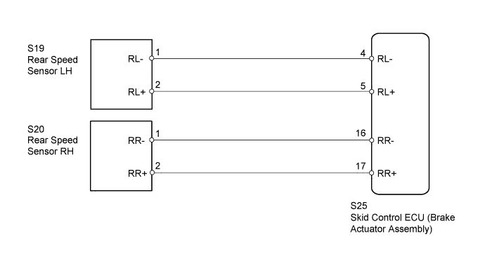
WIRING DIAGRAM
INSPECTION PROCEDURE
- NOTICE:
- When replacing the brake actuator assembly, perform zero point calibration (Toyota Fortuner RM000000XHR02TX.html).
- Check the speed sensor signal in test mode after replacing parts or clearing DTCs (Toyota Fortuner RM000000XHT070X.html).
| 1.CHECK HARNESS AND CONNECTOR (MOMENTARY INTERRUPTION) |
Using the intelligent tester, check for any momentary interruption in the wire harnesses and connectors corresponding to the DTC (Toyota Fortuner RM000000XHS04KX.html).
ABS/VSC/TRCTester Display
| Measurement Item/Range
| Normal Condition
| Diagnostic Note
|
RR Speed Open
| Rear speed sensor RH open detection / Error or Normal
| Normal
| -
|
RL Speed Open
| Rear speed sensor LH open detection / Error or Normal
| Normal
| -
|
- OK:
- Normal (There are no momentary interruptions.)
- HINT:
- Perform the above inspection before removing the sensor and connector.
| 2.READ VALUE USING INTELLIGENT TESTER (RR/RL WHEEL SPEED) |
Turn the ignition switch off.
Connect the intelligent tester to the DLC3.
Start the engine.
Select the Data List mode on the intelligent tester (Toyota Fortuner RM000000XHW080X.html).
ABS/VSC/TRCTester Display
| Measurement Item/Range
| Normal Condition
| Diagnostic Note
|
RR Wheel Speed
| Rear wheel RH speed sensor reading / min.: 0 km/h (0 mph), max.: 326 km/h (202 mph)
| Actual wheel speed
| Similar to speed indicated on speedometer
|
RL Wheel Speed
| Rear wheel LH speed sensor reading / min.: 0 km/h (0 mph), max.: 326 km/h (202 mph)
| Actual wheel speed
| Similar to speed indicated on speedometer
|
Check that there is no significant difference between the speed value displayed on the intelligent tester and the speed value displayed on the speedometer when driving the vehicle.
- HINT:
- Factors that affect the indicated vehicle speed include tire size, tire inflation, and tire wear. The speed indicated on the speedometer has an allowable margin of error. This can be tested using a speedometer tester (calibrated chassis dynamometer). For details about testing and the margin of error, see the reference chart (Toyota Fortuner RM0000011JB00MX.html).
- OK:
- The speed value displayed on the intelligent tester is almost the same as the actual vehicle speed measured using a speedometer tester (calibrated chassis dynamometer).
| 3.PERFORM TEST MODE (SIGNAL CHECK) |
Perform the sensor check in the Test Mode procedure (Toyota Fortuner RM000000XHT070X.html).
- OK:
- All Test Mode DTCs are erased.
Clear the DTC(s) (Toyota Fortuner RM000000XHV09NX.html).
Start the engine.
Drive the vehicle at a speed of 40 km/h (25 mph) or more for at least 60 seconds.
Check if the same DTC is recorded (Toyota Fortuner RM000000XHV09NX.html).
ResultResult
| Proceed to
|
DTC not output
| A
|
DTC output
| B
|
| A |
|
|
|
| CHECK FOR INTERMITTENT PROBLEMS |
|
| 5.CHECK IF SKID CONTROL ECU AND REAR SPEED SENSOR CONNECTORS ARE SECURELY CONNECTED |
Check if the skid control ECU and rear speed sensor connectors are securely connected.
Clear the DTC(s) (Toyota Fortuner RM000000XHV09NX.html).
Start the engine.
Drive the vehicle at a speed of 40 km/h (25 mph) or more for at least 60 seconds.
Check if the same DTC is recorded (Toyota Fortuner RM000000XHV09NX.html).
ResultResult
| Proceed to
|
DTC output
| A
|
DTC not output
| B
|
| 7.CHECK REAR SPEED SENSOR INSTALLATION |
Turn the ignition switch off.
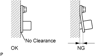
Check the speed sensor installation (Toyota Fortuner RM0000010JQ01HX.html).
- OK:
- The installation bolt is tightened properly and there is no clearance between the speed sensor and rear axle housing.
| | INSTALL REAR SPEED SENSOR CORRECTLY |
|
|
| 8.CHECK REAR SPEED SENSOR TIP |
Remove the rear speed sensor (Toyota Fortuner RM0000010JT015X.html).
Check the speed sensor tip.
- OK:
- No scratches or foreign matter on the sensor tip.
- HINT:
- If the sensor is contaminated with oil or other foreign material, clean the sensor.
- If there is iron powder sticking to the rotor, this will result in a malfunction, so confirm that the rotor is not contaminated with foreign material before replacing the sensor.
- NOTICE:
- Do not replace the speed sensor if no damage to the speed sensor tip is found.
- Check the speed sensor signal after cleaning or replacement (Toyota Fortuner RM000000XHT070X.html).
| | CLEAN OR REPLACE REAR SPEED SENSOR |
|
|
| 9.INSPECT REAR SPEED SENSOR |
Make sure that there is no looseness at the locking part and the connecting part of the connectors.
Disconnect the rear speed sensor connector.
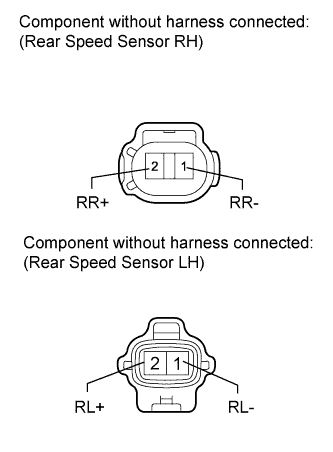
Measure the resistance according to the value(s) in the table below.
- Standard Resistance:
- for RH:
Tester Connection
| Condition
| Specified Condition
|
1 (RR-) - Body ground
| Always
| 10 kΩ or higher
|
2 (RR+) - Body ground
| Always
| 10 kΩ or higher
|
- for LH:
Tester Connection
| Condition
| Specified Condition
|
1 (RL-) - Body ground
| Always
| 10 kΩ or higher
|
2 (RL+) - Body ground
| Always
| 10 kΩ or higher
|
- NOTICE:
- Check the speed sensor signal after replacement (Toyota Fortuner RM000000XHT070X.html).
| | REPLACE REAR SPEED SENSOR |
|
|
| 10.CHECK HARNESS AND CONNECTOR (SKID CONTROL ECU - REAR SPEED SENSOR) |
Disconnect the rear speed sensor connector.
Disconnect the skid control ECU connector.
Measure the resistance according to the value(s) in the table below.
- Standard Resistance:
- for RH:
Tester Connection
| Condition
| Specified Condition
|
S25-17 (RR+) - S20-2 (RR+)
| Always
| Below 1 Ω
|
S25-17 (RR+) - Body ground
| Always
| 10 kΩ or higher
|
S25-16 (RR-) - S20-1 (RR-)
| Always
| Below 1 Ω
|
S25-16 (RR-) - Body ground
| Always
| 10 kΩ or higher
|
- for LH:
Tester Connection
| Condition
| Specified Condition
|
S25-5 (RL+) - S19-2 (RL+)
| Always
| Below 1 Ω
|
S25-5 (RL+) - Body ground
| Always
| 10 kΩ or higher
|
S25-4 (RL-) - S19-1 (RL-)
| Always
| Below 1 Ω
|
S25-4 (RL-) - Body ground
| Always
| 10 kΩ or higher
|
| | REPAIR OR REPLACE HARNESS OR CONNECTOR |
|
|
| 11.INSPECT SKID CONTROL ECU (SENSOR INPUT) |
Disconnect the rear speed sensor connector.
Measure the voltage according to the value(s) in the table below.
- Standard Voltage:
- for RH:
Tester Connection
| Switch Condition
| Specified Condition
|
S20-2 (RR+) - Body ground
| Ignition switch ON
| 8 to 14 V
|
- for LH:
Tester Connection
| Switch Condition
| Specified Condition
|
S19-2 (RL+) - Body ground
| Ignition switch ON
| 8 to 14 V
|
| | REPLACE BRAKE ACTUATOR ASSEMBLY |
|
|
| 12.REPLACE REAR SPEED SENSOR |
Turn the ignition switch off.
Replace the rear speed sensor (Toyota Fortuner RM0000010JT015X.html).
- NOTICE:
- Check the speed sensor signal after replacement (Toyota Fortuner RM000000XHT070X.html).
Clear the DTC(s) (Toyota Fortuner RM000000XHV09NX.html).
Start the engine.
Drive the vehicle at a speed of 40 km/h (25 mph) or more for at least 60 seconds.
Check if the same DTC is recorded (Toyota Fortuner RM000000XHV09NX.html).
ResultResult
| Proceed to
|
DTC output
| A
|
DTC not output
| B
|
- HINT:
- If troubleshooting has been carried out according to the Problem Symptoms Table, refer back to the table and proceed to the next step (Toyota Fortuner RM000000XHN092X.html).
| 14.REPLACE REAR SKID CONTROL ROTOR |
Turn the ignition switch off.
Replace the rear skid control rotor (Toyota Fortuner RM000000ZZV00LX.html).
- NOTICE:
- Check the speed sensor signal after replacement (Toyota Fortuner RM000000XHT070X.html).
Clear the DTC(s) (Toyota Fortuner RM000000XHV09NX.html).
Start the engine.
Drive the vehicle at a speed of 40 km/h (25 mph) or more for at least 60 seconds.
Check if the same DTC is recorded (Toyota Fortuner RM000000XHV09NX.html).
ResultResult
| Proceed to
|
DTC not output
| A
|
DTC output
| B
|
- HINT:
- If troubleshooting has been carried out according to the Problem Symptoms Table, refer back to the table and proceed to the next step (Toyota Fortuner RM000000XHN092X.html).
| | REPLACE BRAKE ACTUATOR ASSEMBLY |
|
|