Vehicle Stability Control System -- Test Mode Procedure |
| WARNING LIGHT AND INDICATOR LIGHT INITIAL CHECK |
Release the parking brake.
- NOTICE:
- Before releasing the parking brake, move the shift lever to the P position (for A/T) or set chocks to hold the vehicle (for M/T) for safety.
- HINT:
- When the parking brake is applied or the level of the brake fluid is low, the brake warning light comes on.
When the ignition switch is turned to ON, check that the ABS warning, brake warning, VSC OFF indicator, and slip indicator lights come on for approximately 3 seconds.
- HINT:
- If the skid control ECU stores any DTCs, the ABS warning, brake warning, and slip indicator lights will come on and the VSC OFF indicator light will blink.
- If any of the indicators remains on or does not come on, proceed to troubleshooting for the light circuits listed below.
Trouble Area See Procedure ABS warning light circuit (Remains on) Toyota Fortuner RM000003O4G003X.html ABS warning light circuit (Does not come on) Toyota Fortuner RM000003O4H003X.html Brake warning light circuit (Remains on) Toyota Fortuner RM000003O4I003X.html Brake warning light circuit (Does not come on) Toyota Fortuner RM000003O4J003X.html VSC OFF indicator light circuit (Remains on) Toyota Fortuner RM000003O4M003X.html VSC OFF indicator light circuit (Does not come on) Toyota Fortuner RM000003O4N003X.html Slip indicator light circuit (Remains on) Toyota Fortuner RM000003O4K003X.html Slip indicator light circuit (Does not come on) Toyota Fortuner RM000003O4L003X.html
 |
| SENSOR CHECK USING TEST MODE (SIGNAL CHECK) (When Using Intelligent Tester) |
- NOTICE:
- After replacement of the brake actuator assembly and/or yaw rate sensor, perform zero point calibration of the yaw rate and acceleration sensor.
- HINT:
- If the ignition switch is turned from ON to ACC or off during Test Mode (signal check), DTCs recorded during the sensor check will be erased.
- During Test Mode (signal check), the skid control ECU records all DTCs detected in the sensor check. By performing Test Mode (signal check), the codes are erased if a normal condition is confirmed. The remaining codes are the codes indicating where an abnormality was found.
Procedure to enter Test Mode
Turn the ignition switch off.
Check that the steering wheel is in the straight-ahead position.
for A/T:
Check that the shift lever is in the P position and apply the parking brake.
for M/T:
Check that the shift lever is in neutral and apply the parking brake.Connect the intelligent tester to the DLC3.
Turn the ignition switch to ON.
Turn the intelligent tester on.
Switch the skid control ECU to Test Mode using the intelligent tester. Enter the following menus: Chassis / ABS/VSC/TRC / Signal Check.
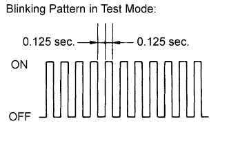
Check that the ABS warning and VSC OFF indicator lights come on for several seconds and then blink in the Test Mode blinking pattern.
- HINT:
- If the ABS warning and VSC OFF indicator lights do not blink, inspect the TS and CG terminal circuit and ABS warning and VSC OFF indicator light circuits.
Lost Booster Pressure Judgement Check and Master Cylinder Pressure Sensor Zero Point Calibration
- NOTICE:
- Perform the check in the lost booster pressure state (vacuum in the booster has decreased).
Turn the ignition switch to ON.
Check that the brake warning light comes on when depressing the brake pedal with a force greater than 59 N (6 kgf, 13.2 lbf) for 1 second or more. (The lost booster pressure state is judged as normal.)
While depressing the brake pedal with a force greater than 59 N (6 kgf, 13.2 lbf), start the engine.
Check that the brake warning light goes off when quickly releasing the brake pedal. (The lost booster pressure state is judged as normal.)
Leave the vehicle for 1 second or more. (Master cylinder pressure sensor zero point calibration)
- NOTICE:
- If you slowly release the brake pedal or depress it again, master cylinder pressure sensor zero point calibration is not performed normally.
- If the lost booster pressure judgement check results are not normal, then the master cylinder pressure sensor check will not be able to be performed.
- If a recheck is performed after the engine has started, end Test Mode, transit to Test Mode again, and release vacuum in the booster by pumping the brake pedal prior to the recheck.
Acceleration Sensor Check
Keep the vehicle stationary on a level surface for 1 second or more.
- HINT:
- The acceleration sensor check can be performed with the master cylinder pressure sensor check below.
Master Cylinder Pressure Sensor Check
Leave the vehicle in a stationary condition and release the brake pedal for 1 second or more, and then quickly and continuously depress the brake pedal with a force greater than 98 N (10 kgf, 22 lbf) for 1 second.
Check that the ABS warning light stays on for 3 seconds.
- HINT:
- The ABS warning light comes on for 3 seconds every time brake pedal operation above is performed.
- If the master cylinder pressure sensor check is not completed, depressing the brake pedal causes further decreases in vacuum in the brake booster, making the sensor check difficult to complete.
- If the vacuum is insufficient, the master cylinder pressure sensor check may not be completed. In this case, run the engine at idle to obtain sufficient vacuum.
- If the brake pedal is strongly depressed when the vacuum is insufficient, the brake warning light may come on in accordance with booster pressure control. In this case, run the engine at idle to obtain sufficient vacuum.
for 4WD:
Center Differential Lock Position Switch Signal Check.Move the transfer high and low shift lever to the center differential lock position.
Move the transfer high and low shift lever to the center differential free position.
Speed Sensor Check
- NOTICE:
- Before performing the speed sensor signal check, complete the acceleration sensor, master cylinder pressure sensor and center differential lock detection switch signal checks.
Check that the ABS warning light is blinking as shown in the illustration.
Check the speed sensor signal.

- Drive the vehicle straight forward at a speed of 45 km/h (28 mph) or more for several seconds.
- Check that the ABS warning light goes off.
- HINT:
- The speed sensor check may not be completed if the sensor check is started with the steering wheel turned or one or more wheels spinning.
- If the speed sensor check is commenced while the steering wheel is turned, the ABS warning light may come on after the speed sensor check is finished.
- The ABS warning light comes on immediately when an abnormality is detected.
- When the speed sensor signal is normal, the ABS warning light goes off while driving at 45 km/h (28 mph) or more and blinks in the test mode pattern while stationary.
- After the ABS warning light goes off and if the vehicle speed exceeds 80 km/h (50 mph), a sensor check code will be stored again. Decelerate or stop the vehicle before the speed reaches 80 km/h (50 mph).
- If the vehicle is driven on extremely rough or bumpy roads, the sensor signal check may fail and middle speed check DTCs may not be cleared. In such cases, stop the vehicle and drive it again to resume the speed sensor check.
- Drive the vehicle straight forward at a speed of 45 km/h (28 mph) or more for several seconds.
Check that the VSC OFF indicator light is blinking in the Test Mode blinking pattern.
Yaw Rate Sensor Check
Keep the vehicle in a stationary condition on a level surface for 1 second or more.
Drive the vehicle at a speed of approximately 5 km/h (3 mph), and turn the steering wheel either to the left or right 90° or more until the vehicle makes a 180° turn.
for A/T:
Stop the vehicle and move the shift lever to the P position and apply the parking brake. Check that the skid control buzzer sounds for 3 seconds.
for M/T:
Stop the vehicle, move the shift lever to neutral and apply the parking brake. Check that the skid control buzzer sounds for 3 seconds.- HINT:
- If the skid control buzzer sounds, the sensor check has completed normally.
- If the skid control buzzer does not sound, check the skid control buzzer circuit (Toyota Fortuner RM000000XIS03FX.html), and then perform the sensor check again. If the skid control buzzer still does not sound, the yaw rate sensor may be malfunctioning. Check for DTCs.
- Make a 180° turn. At the end of the turn, the direction of the vehicle should be within 180° +/-5° of its start position.
- Do not allow the wheels to spin.
- Do not turn the ignition switch off while turning.
- for A/T:
Do not move the shift lever to the P position while turning, but changing the vehicle speed, stopping, or driving in reverse is acceptable. - for M/T:
Do not apply the parking brake while turning, but changing the vehicle speed, stopping, or driving in reverse is acceptable. - Complete the turn within 20 seconds.

VSC OFF Switch Check
Briefly press the VSC OFF switch.
Check that the slip indicator light goes off.
Briefly press the VSC OFF switch again to turn the slip indicator light on.
End of Sensor Check
If the sensor check is completed, the ABS warning light blinks (Test Mode) when the vehicle is stopped and goes off while the vehicle is driven.
- NOTICE:
- When the yaw rate sensor, acceleration sensor, speed sensor, and master cylinder pressure sensor checks are completed, the sensor check is completed.
- If the sensor check is not completed, the ABS warning light will blink even while the vehicle is driven and the ABS will not operate.
Read Sensor Check DTCs
Read the DTC(s) by following the tester screen.
- NOTICE:
- If only DTCs other than Test Mode sensor check DTCs are displayed, repair the malfunctions and clear the DTCs.
- If Test Mode sensor check DTCs and other DTCs are displayed or if only Test Mode sensor check DTCs are displayed, repair the malfunctions, clear the DTCs, and perform Test Mode inspection again.
- HINT:
- Refer to "Sensor Check DTCs".
Turn the ignition switch off and disconnect the intelligent tester.
Sensor Check DTCs
ABS Sensor: DTC Code Detection Item Trouble Area C1271 Low Output Signal of Front Speed Sensor RH - Front speed sensor RH
- Sensor installation
- Front skid control rotor RH
C1272 Low Output Signal of Front Speed Sensor LH - Front speed sensor LH
- Sensor installation
- Front skid control rotor LH
C1273 Low Output Signal of Rear Speed Sensor RH - Rear speed sensor RH
- Sensor installation
- Rear skid control rotor RH
C1274 Low Output Signal of Rear Speed Sensor LH - Rear speed sensor LH
- Sensor installation
- Rear skid control rotor LH
C1275 Abnormal Change in Output Signal of Front Speed Sensor RH Front skid control rotor RH C1276 Abnormal Change in Output Signal of Front Speed Sensor LH Front skid control rotor LH C1277 Abnormal Change in Output Signal of Rear Speed Sensor RH Rear skid control rotor RH C1278 Abnormal Change in Output Signal of Rear Speed Sensor LH Rear skid control rotor LH C1279 Acceleration Sensor Output Voltage Malfunction - Yaw rate and acceleration sensor (Yaw rate sensor assembly)
- Sensor installation
C1281 Master Cylinder Pressure Sensor Output Malfunction - Stop light switch
- Master cylinder pressure sensor (Brake actuator assembly)
C1282 Center differential lock position switch malfunction - Center differential lock position switch (Transfer indicator switch No. 3)
- Center differential lock position switch circuit
- Skid control ECU (Brake actuator assembly)
VSC Sensor: DTC Code Detection Item Trouble Area C0371 Yaw Rate Sensor Yaw rate and acceleration sensor (Yaw rate sensor assembly) - HINT:
- The codes in these table are stored only in Test Mode (signal check).
- Front speed sensor RH
| SENSOR CHECK USING TEST MODE (SIGNAL CHECK) (When not Using Intelligent Tester) |
- NOTICE:
- After replacement of the brake actuator assembly and/or yaw rate and acceleration sensor, perform zero point calibration of the yaw rate and acceleration sensor.
- HINT:
- If the ignition switch is turned from ON to ACC or off during Test Mode (signal check), DTCs recorded during the sensor check will be erased.
- During Test Mode (signal check), the skid control ECU records all DTCs detected in the sensor check. By performing Test Mode (signal check), the codes are erased if a normal condition is confirmed. The remaining codes are the codes indicating where an abnormality was found.
Procedure to enter Test Mode
Turn the ignition switch off.
Check that the steering wheel is in the straight-ahead position.
for A/T:
Check that the shift lever is in the P position and apply the parking brake.
for M/T:
Check that the shift lever is in neutral and apply the parking brake.Using SST, connect terminals 12 (TS) and 4 (CG) of the DLC3.
- SST
- 09843-18040
Turn the ignition switch to ON.
Check that the ABS warning and VSC OFF indicator lights come on for several seconds and then blink in the Test Mode blinking pattern.
- HINT:
- If the ABS warning and VSC OFF indicator lights do not blink, inspect the TS and CG terminal circuit and ABS warning and VSC OFF indicator light circuits.

Lost Booster Pressure Judgement Check and Master Cylinder Pressure Sensor Zero Point Calibration
- NOTICE:
- Perform the check in the lost booster pressure state (vacuum in the booster has decreased).
Turn the ignition switch to ON.
Check that the brake warning light comes on when depressing the brake pedal with a force greater than 59 N (6 kgf, 13.2 lbf) for 1 second or more. (The lost booster pressure state is judged as normal.)
While depressing the brake pedal with a force greater than 59 N (6 kgf, 13.2 lbf), start the engine.
Check that the brake warning light goes off when quickly releasing the brake pedal. (The lost booster pressure state is judged as normal.)
Leave the vehicle for 1 second or more. (Master cylinder pressure sensor zero point calibration)
- NOTICE:
- If you slowly release the brake pedal or depress it again, master cylinder pressure sensor zero point calibration is not performed normally.
- If the lost booster pressure judgement check results are not normal, then the master cylinder pressure sensor check will not be able to be performed.
- If a recheck is performed after the engine has started, end Test Mode, transit to Test Mode again, and release vacuum in the booster by pumping the brake pedal prior to the recheck.
Acceleration Sensor Check
Keep the vehicle stationary on a level surface for 1 second or more.
- HINT:
- The acceleration sensor check can be performed with the master cylinder pressure sensor check below.
Master Cylinder Pressure Sensor Check
Leave the vehicle in a stationary condition and release the brake pedal for 1 second or more, and then quickly and continuously depress the brake pedal with a force greater than 98 N (10 kgf, 22 lbf) for 1 second.
Check that the ABS warning light stays on for 3 seconds.
- HINT:
- The ABS warning light comes on for 3 seconds every time the brake pedal operation above is performed.
- If the master cylinder pressure sensor check is not completed, depressing the brake pedal causes further decreases in vacuum in the brake booster, making the sensor check difficult to complete.
- If the vacuum is insufficient, the master cylinder pressure sensor check may not be completed. In this case, run the engine at idle to obtain sufficient vacuum.
- If the brake pedal is strongly depressed when the vacuum is insufficient, the brake warning light may come on in accordance with booster pressure control. In this case, run the engine at idle to obtain sufficient vacuum.
for 4WD:
Center Differential Lock Position Switch Signal Check.Move the transfer high and low shift lever to the center differential lock position.
Move the transfer high and low shift lever to the center differential free position.
Speed Sensor Check
- NOTICE:
- Before performing the speed sensor signal check, complete the acceleration sensor, master cylinder pressure sensor and center differential lock detection switch signal checks.
Check that the ABS warning light is blinking as shown in the illustration.
Check the speed sensor signal.
- Drive the vehicle straight forward at a speed of 45 km/h (28 mph) or more for several seconds.
- Check that the ABS warning light goes off.
- HINT:
- The speed sensor check may not be completed if the sensor check is started with the steering wheel turned or one or more wheels spinning.
- If the speed sensor check is commenced while the steering wheel is turned, the ABS warning light may come on after the speed sensor check is finished.
- The ABS warning light comes on immediately when an abnormality is detected.
- When the speed sensor signal is normal, the ABS warning light goes off while driving at 45 km/h (28 mph) or more and blinks in the test mode pattern while stationary.
- After the ABS warning light goes off, if the vehicle speed exceeds 80 km/h (50 mph), a sensor check code will be stored again. Decelerate or stop the vehicle before the speed reaches 80 km/h (50 mph).
- If the vehicle is driven on extremely rough or bumpy roads, the sensor signal check may fail and middle speed check DTCs may not be cleared. In such cases, stop the vehicle and drive it again to resume the speed sensor check.
- Drive the vehicle straight forward at a speed of 45 km/h (28 mph) or more for several seconds.
Check that the VSC OFF indicator light is blinking in the Test Mode blinking pattern.
Yaw Rate Sensor Check
Keep the vehicle in a stationary condition on a level surface for 1 second or more.
Drive the vehicle at a speed of approximately 5 km/h (3 mph), and turn the steering wheel either to the left or right 90° or more until the vehicle makes a 180° turn.
for A/T:
Stop the vehicle and move the shift lever to the P position and apply the parking brake. Check that the skid control buzzer sounds for 3 seconds.
for M/T:
Stop the vehicle, move the shift lever to neutral and apply the parking brake. Check that the skid control buzzer sounds for 3 seconds.- HINT:
- If the skid control buzzer sounds, the sensor check has completed normally.
- If the skid control buzzer does not sound, check the skid control buzzer circuit (Toyota Fortuner RM000000XIS03FX.html), and then perform the sensor check again. If the skid control buzzer still does not sound, the yaw rate sensor may be malfunctioning. Check for DTCs.
- Make a 180° turn. At the end of the turn, the direction of the vehicle should be within 180° +/-5° of its start position.
- Do not allow the wheels to spin.
- Do not turn the ignition switch off while turning.
- for A/T:
Do not move the shift lever to the P position while turning, but changing the vehicle speed, stopping, or driving in reverse is acceptable. - for M/T:
Do not apply the parking brake while turning, but changing the vehicle speed, stopping, or driving in reverse is acceptable. - Complete the turn within 20 seconds.
VSC OFF Switch Check
Briefly press the VSC OFF switch.
Check that the slip indicator light goes off.
Briefly press the VSC OFF switch again to turn the slip indicator light on.
End of Sensor Check
If the sensor check is completed, the ABS warning light blinks (Test Mode) when the vehicle is stopped and goes off while the vehicle is driven.
- NOTICE:
- When the yaw rate sensor, acceleration sensor, speed sensor, and master cylinder pressure sensor checks are completed, the sensor check is completed.
- If the sensor check is not completed, the ABS warning light will blink even while the vehicle is driven and the ABS will not operate.
Read Sensor Check DTCs
Using SST, connect terminals 12 (TS), 13 (TC) and 4 (CG ) of the DLC3.
- SST
- 09843-18040
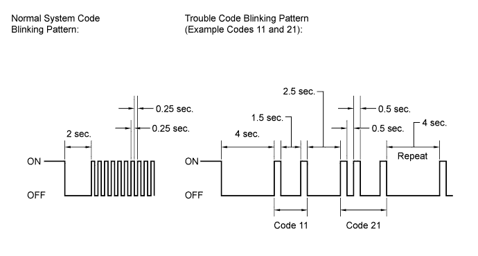
Count the number of blinks of the ABS warning and VSC OFF indicator lights.
- NOTICE:
- If only DTCs other than Test Mode sensor check DTCs are displayed, repair the malfunctions and clear the DTCs.
- If Test Mode sensor check DTCs and other DTCs are displayed or if only Test Mode sensor check DTCs are displayed, repair the malfunctions, clear the DTCs, and perform Test Mode inspection again.
- HINT:
- If more than 1 malfunction is detected at the same time, the lowest numbered code will be displayed first.
- Refer to "Sensor Check DTCs".
After performing the check, disconnect SST from terminals TS and CG, and TC and CG of the DLC3 and turn the ignition switch off.
Turn the ignition switch to ON.
- HINT:
- If the ignition switch is not turned ON after SST is removed from the DLC3, the previous Test Mode will continue.
- If the ignition switch is turned ON with terminals TS and CG connected, the previous Test Mode will continue.

Sensor Check DTCs
ABS Sensor: DTC Code Detection Item Trouble Area 71 Low Output Signal of Front Speed Sensor RH - Front speed sensor RH
- Sensor installation
- Front skid control rotor RH
72 Low Output Signal of Front Speed Sensor LH - Front speed sensor LH
- Sensor installation
- Front skid control rotor LH
73 Low Output Signal of Rear Speed Sensor RH - Rear speed sensor RH
- Sensor installation
- Rear skid control rotor RH
74 Low Output Signal of Rear Speed Sensor LH - Rear speed sensor LH
- Sensor installation
- Rear skid control rotor LH
75 Abnormal Change in Output Signal of Front Speed Sensor RH Front skid control rotor RH 76 Abnormal Change in Output Signal of Front Speed Sensor LH Front skid control rotor LH 77 Abnormal Change in Output Signal of Rear Speed Sensor RH Rear skid control rotor RH 78 Abnormal Change in Output Signal of Rear Speed Sensor LH Rear skid control rotor LH 79 Acceleration Sensor Output Voltage Malfunction - Yaw rate and acceleration sensor (Yaw rate sensor assembly)
- Sensor installation
81 Master Cylinder Pressure Sensor Output Malfunction - Stop light switch
- Master cylinder pressure sensor (Brake actuator assembly)
82 Center differential lock position switch malfunction - Center differential lock position switch (Transfer indicator switch No. 3)
- Center differential lock position switch circuit
- Skid control ECU (Brake actuator assembly)
VSC Sensor: DTC Code Detection Item Trouble Area 71 Yaw Rate Sensor Yaw rate and acceleration sensor (Yaw rate sensor assembly) - HINT:
- The codes in these table are output only in Test Mode (signal check).
- Front speed sensor RH