Dtc C1268 Transfer L4 Position Switch Circuit
DESCRIPTION
WIRING DIAGRAM
INSPECTION PROCEDURE
CHECK TERMINAL VOLTAGE (EXI4 TERMINAL)
RECONFIRM DTC
CHECK HARNESS AND CONNECTOR (EXI4 CIRCUIT)
INSPECT LL POSITION SWITCH
CHECK TERMINAL VOLTAGE (LL POSITION SWITCH POWER SOURCE CIRCUIT)
CHECK HARNESS AND CONNECTOR (SKID CONTROL ECU - ECM)
CHECK HARNESS AND CONNECTOR (SKID CONTROL ECU - TRANSMISSION CONTROL ECU)
DTC C1268 Transfer L4 Position Switch Circuit |
DESCRIPTION
DTC Code
| DTC Detection Condition
| Trouble Area
|
C1268
| No signal is input to the EXI4 terminal of the skid control ECU.
| - LL position switch (No. 1 transfer indicator switch)
- LL position switch circuit
- Transmission control ECU assembly
- Skid control ECU (Brake actuator assembly)
|
WIRING DIAGRAM
INSPECTION PROCEDURE
- NOTICE:
- After replacing the brake actuator assembly, perform calibration (Toyota Fortuner RM000000XHR06WX.html).
- Before disconnecting the connector, make sure that there are no problems with the connection.
- After disconnecting the connector, make sure that the connector case and terminals are not deformed or corroded.
| 1.CHECK TERMINAL VOLTAGE (EXI4 TERMINAL) |
Connect the skid control ECU (brake actuator assembly) connector.
Set the vehicle to the HL or H state using the transfer shift lever.
Disconnect the skid control ECU (brake actuator assembly) connector.
Measure the voltage according to the value(s) in the table below.
- Standard Voltage:
Tester Connection
| Condition
| Specified Condition
|
S25-9 (EXI4) - Body ground
| - Ignition switch ON
- Transfer shift position HL or H
| 11 to 14 V
|
Connect the skid control ECU (brake actuator assembly) connector.
Set the vehicle to the LL state using the transfer shift lever.
Disconnect the skid control ECU (brake actuator assembly) connector.
Measure the voltage according to the value(s) in the table below.
- Standard Voltage:
Tester Connection
| Condition
| Specified Condition
|
S25-9 (EXI4) - Body ground
| - Ignition switch ON
- Transfer shift position LL
| Below 1.5 V
|
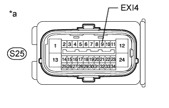
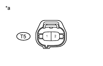
Text in Illustration*a
| Front view of wire harness connector
(to Skid Control ECU [Brake Actuator Assembly])
|
Clear the DTC (Toyota Fortuner RM000000XHV0C7X.html).
Turn the ignition switch off.
Check if the same DTC is output.
ResultResult
| Proceed to
|
DTC is output
| A
|
DTC is not output
| B
|
| 3.CHECK HARNESS AND CONNECTOR (EXI4 CIRCUIT) |
Turn the ignition switch off.
Disconnect the skid control ECU (brake actuator assembly) connector.
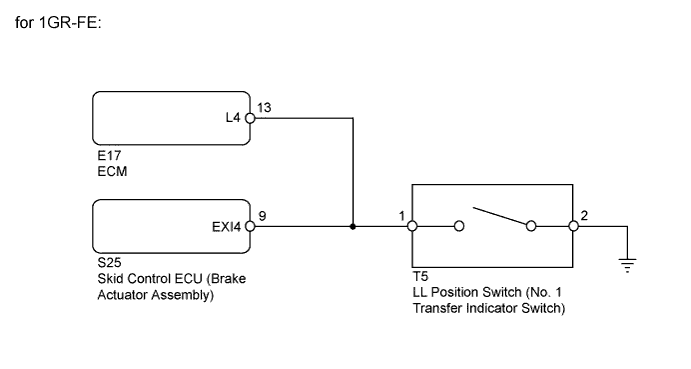
for 1GR-FE:
Disconnect the E17 ECM connector.
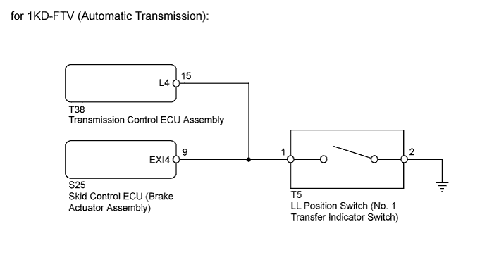
for 1KD-FTV (Automatic Transmission):
Disconnect the T38 transmission control ECU connector.
Disconnect the LL position switch (No. 1 transfer indicator switch) connector.
Measure the resistance according to the value(s) in the table below.
- Standard Resistance:
Tester Connection
| Condition
| Specified Condition
|
S25-9 (EXI4) - T5-1
| Always
| Below 1 Ω
|
S25-9 (EXI4) - Body ground
| Always
| 10 kΩ or higher
|
T5-2 - Body ground
| Always
| Below 1 Ω
|
| | REPAIR OR REPLACE HARNESS OR CONNECTOR |
|
|
| 4.INSPECT LL POSITION SWITCH |
Turn the ignition switch off.
Remove the LL position switch (No. 1 transfer indicator switch) (Toyota Fortuner RM000001HGX001X.html).
Inspect the LL position switch (No. 1 transfer indicator switch) (Toyota Fortuner RM000001TFE000X.html).
| | REPLACE NO. 1 TRANSFER INDICATOR SWITCH |
|
|
| 5.CHECK TERMINAL VOLTAGE (LL POSITION SWITCH POWER SOURCE CIRCUIT) |
Turn the ignition switch off.
Disconnect the LL position switch (No. 1 transfer indicator switch) connector.
Disconnect the skid control ECU (brake actuator assembly) connector.
for 1GR-FE:
Connect the ECM connector.
for 1KD-FTV (Automatic Transmission):
Connect the transmission control ECU connector.
Measure the voltage according to the value(s) in the table below.
- Standard Voltage:
Tester Connection
| Switch Condition
| Specified Condition
|
1 - 2
| Ignition switch ON
| 11 to 14 V
|
Text in Illustration*a
| Front view of wire harness connector
(to LL Position Switch [No. 1 Transfer Indicator Switch])
|
ResultResult
| Proceed to
|
OK
| A
|
NG
| for 1GR-FE
| B
|
for 1KD-FTV (Automatic Transmission)
| C
|
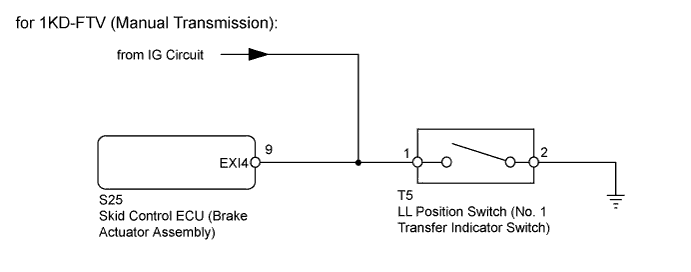
for 1KD-FTV (Manual Transmission)
| D
|
| |
|
| |
|
| | REPAIR OR REPLACE HARNESS OR CONNECTOR |
|
|
| 6.CHECK HARNESS AND CONNECTOR (SKID CONTROL ECU - ECM) |
Turn the ignition switch off.
Disconnect the skid control ECU (brake actuator assembly) connector.
Disconnect the E17 ECM connector.
Disconnect the LL position switch (No. 1 transfer indicator switch) connector.
Measure the resistance according to the value(s) in the table below.
- Standard Resistance:
Tester Connection
| Condition
| Specified Condition
|
S25-9 (EXI4) - E17-13 (L4)
| Always
| Below 1 Ω
|
S25-9 (EXI4) - Body ground
| Always
| 10 kΩ or higher
|
| | REPAIR OR REPLACE HARNESS OR CONNECTOR |
|
|
| 7.CHECK HARNESS AND CONNECTOR (SKID CONTROL ECU - TRANSMISSION CONTROL ECU) |
Turn the ignition switch off.
Disconnect the skid control ECU (brake actuator assembly) connector.
Disconnect the T38 transmission control ECU connector.
Disconnect the LL position switch (No. 1 transfer indicator switch) connector.
Measure the resistance according to the value(s) in the table below.
- Standard Resistance:
Tester Connection
| Condition
| Specified Condition
|
S25-9 (EXI4) - T38-15 (L4)
| Always
| Below 1 Ω
|
S25-9 (EXI4) - Body ground
| Always
| 10 kΩ or higher
|
| | REPAIR OR REPLACE HARNESS OR CONNECTOR |
|
|
| OK |
|
|
|
| REPLACE TRANSMISSION CONTROL ECU ASSEMBLY |
|