Oil Pump -- Installation |
| 1. INSTALL TIMING BELT CASE SUB-ASSEMBLY |
Place a new gasket on the cylinder block.
Install the timing belt case with the 5 bolts.
- Torque:
- 22.5 N*m{229 kgf*cm, 17 ft.*lbf}
 |
| 2. INSTALL OIL STRAINER SUB-ASSEMBLY |
Install a new gasket and oil strainer with the 2 bolts and 2 nuts.
- Torque:
- 21 N*m{214 kgf*cm, 15 ft.*lbf}for nut
- 18 N*m{184 kgf*cm, 13 ft.*lbf}for bolt
| 3. INSTALL OIL PAN SUB-ASSEMBLY |
Using a gasket scraper, remove all the old seal packing material from the installation surface of the oil pan and cylinder block.
- Thoroughly clean all components to remove all the loose material.
- Using a non-residue solvent, clean both of the sealing surfaces.
- NOTICE:
- Do not use a solvent which will affect the painted surfaces.
- Do not apply any oil on the contact surfaces of the oil pan and cylinder block.
- Thoroughly clean all components to remove all the loose material.
Remove any old seal packing material and do not drop any oil on the contact surfaces of the oil pan and cylinder block.
Apply seal packing to the oil pan as shown in the illustration.
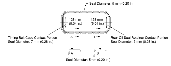
- Seal packing:
- Toyota Genuine Seal Packing Black, Three Bond 1207B or equivalent
- Standard seal diameter:
- 5 mm (0.20 in.)
- 7 mm (0.28 in.) for timing belt case contact portion
- 7 mm (0.28 in.) for rear oil seal retainer contact portion
- HINT:
- Do not apply an excessive amount to the surface, especially near the oil passages.
- Parts must be assembled within 5 minutes of application. Otherwise the material must be removed and reapplied.
- After application, immediately remove the nozzle from the tube and reinstall the cap.
Install the oil pan with the 16 bolts and 2 nuts. Uniformly tighten the bolts and nuts in several steps.
- Torque:
- 18 N*m{184 kgf*cm, 13 ft.*lbf}
| 4. INSTALL CRANKSHAFT TIMING PULLEY |
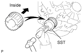
Align the pulley set key with the key groove of the timing pulley.
Using SST and a hammer, tap in the timing pulley, facing the flange side inward.
- SST
- 09223-46011
 |
| 5. INSTALL NO. 2 TIMING BELT IDLER SUB-ASSEMBLY |
Install the spacer and No. 2 timing belt idler with the bolt.
- Torque:
- 33 N*m{337 kgf*cm, 24 ft.*lbf}
Check that the No. 2 timing belt idler moves smoothly.
| 6. INSTALL NO. 1 TIMING BELT IDLER SUB-ASSEMBLY |
Temporarily install the No. 1 timing belt idler with the 3 bolts labeled A, B and C.
 |
Tighten the bolt C.
- Torque:
- 19 N*m{194 kgf*cm, 14 ft.*lbf}
- HINT:
The bolt lengths for bolts A, B and C as follows.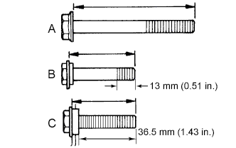
- A:
- 76.5 mm (3.012 in.)
- B:
- 42.9 mm (1.689 in.)
- C:
- 41.3 mm (1.626 in.)
- Bolt C is combined with the No. 1 timing belt idler.
| 7. INSTALL WATER PUMP ASSEMBLY |
Install a new gasket, the water pump and tension spring bracket with the 6 bolts.
- Torque:
- 23 N*m{235 kgf*cm, 17 ft.*lbf}
 |
| 8. INSTALL NO. 2 TIMING BELT COVER |
Install the timing belt cover with the 4 bolts.
- Torque:
- 18 N*m{184 kgf*cm, 13 ft.*lbf}
| 9. INSTALL CAMSHAFT TIMING PULLEY |
Install the woodruff key to the key groove of the camshaft.
Align the pulley set key with the timing mark facing outward.
Using SST, install the pulley with the bolt.
- SST
- 09960-10010(09962-01000,09963-01000)
- Torque:
- 98 N*m{1,000 kgf*cm, 72 ft.*lbf}
 |
| 10. INSTALL INJECTION PUMP ASSEMBLY |
Install the injection pump to the timing gear case, and temporarily tighten the 2 nuts.
 |
Install the injection pump stay to the injection pump rear end, and temporarily tighten the 3 bolts.
Rotate the pump body to align the markings of the pump flange and timing gear case.
 |
Tighten the 2 nuts to install the injection pump.
- Torque:
- 21 N*m{210 kgf*cm, 15 ft.*lbf}
Tighten the 3 bolts to install the injection pump stay.
- Torque:
- 26 N*m{265 kgf*cm, 19 ft.*lbf}for injection pump stay to cylinder block
- 26 N*m{265 kgf*cm, 19 ft.*lbf}for injection pump stay to injection pump
Connect the 3 fuel hoses.
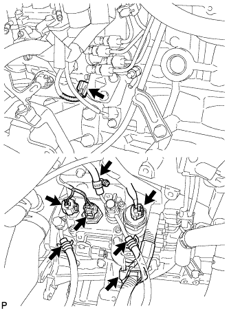 |
Connect the engine speed sensor connector.
Connect the spill control valve connector.
Connect the correction unit connector.
Connect the timing control valve connector.
Connect the fuel temperature sensor connector.
Connect the engine wire clamp.
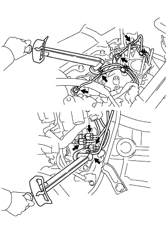
| 11. INSTALL INJECTION PUMP DRIVE PULLEY |
Using SST, install the injection pump drive pulley with the nut.
- SST
- 09213-14010(91651-60865)
09330-00021
- Torque:
- 64 N*m{650 kgf*cm, 47 ft.*lbf}
 |
| 12. INSTALL INJECTION PIPE SUB-ASSEMBLY |
Connect the 2 lower pipe clamps onto the intake manifold.
 |
Install the 4 injection pipes.
- Torque:
- 25 N*m{250 kgf*cm, 18 ft.*lbf}
- NOTICE:
- Use the formula to calculate special torque values for situations where a union nut wrench is combined with a torque wrench (Toyota Fortuner RM000000UYX010X.html).
Secure the injection pipes with the 2 upper pipe clamps and 2 nuts.
- Torque:
- 5.0 N*m{51 kgf*cm, 44 in.*lbf}
| 13. INSTALL TIMING BELT |
Install the timing belt (Toyota Fortuner RM00000126H002X.html).
| 14. INSTALL ENGINE ASSEMBLY |
Install the engine assembly (Toyota Fortuner RM000000FYK004X.html).