INSTALL COMPRESSOR MOUNTING BRACKET (w/ Air Conditioning System)
INSTALL FAN BELT ADJUSTING BAR (w/o Air Conditioning System)
INSTALL COMPRESSOR AND MAGNET CLUTCH (w/ Air Conditioning System)
INSTALL FAN & GENERATOR V BELT (w/o Air Conditioning System)
INSTALL COOLER COMPRESSOR V BELT (w/ Air Conditioning System)
Engine Assembly -- Installation |
| 1. INSTALL WIRE HARNESS CLAMP BRACKET |
Install the wire harness clamp bracket with the bolt.
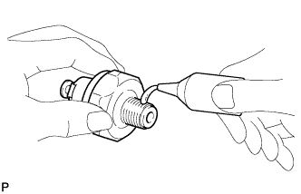
| 2. INSTALL ENGINE OIL PRESSURE SWITCH ASSEMBLY |
Clean the threads of the oil pressure switch, and apply adhesive to them.
- Adhesive:
- Toyota Genuine Adhesive 1344, Three Bond 1344 or equivalent
 |
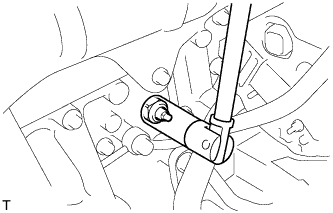
Using a 24 mm deep socket wrench, install the oil pressure switch.
- Torque:
- 15 N*m{155 kgf*cm, 11 ft.*lbf}
 |
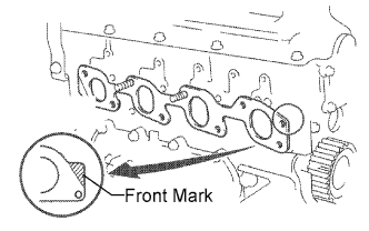
| 3. INSTALL EXHAUST MANIFOLD |
Install a new gasket to the cylinder head.
- HINT:
- Be sure to install a new gasket in the correct direction as shown in the illustration.
 |
Install the exhaust manifold with the 6 bolts and 2 new nuts. Uniformly tighten the bolts and nuts in several steps.
- Torque:
- 52 N*m{530 kgf*cm, 38 ft.*lbf}
 |
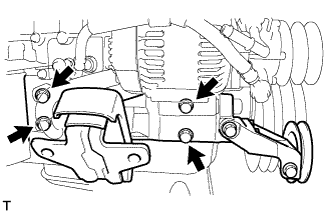
| 4. INSTALL NO. 1 FRONT ENGINE MOUNTING BRACKET RH |
Install the engine mounting bracket with the 4 bolts.
- Torque:
- 49 N*m{500 kgf*cm, 36 ft.*lbf}
 |
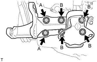
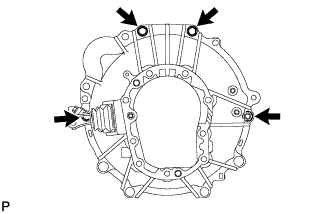
| 5. INSTALL PUMP BRACKET |
Install the pump bracket with the 6 bolts.
- Torque:
- 78 N*m{795 kgf*cm, 58 ft.*lbf}for bolt A
- 57 N*m{581 kgf*cm, 42 ft.*lbf}for bolt B
 |
| 6. INSTALL WATER BY-PASS HOSE UNION |
Clean the threads of the water by-pass hose union, and apply adhesive to them.
- Adhesive:
- Toyota Genuine Adhesive 1324, Three Bond 1324 or equivalent
Install the water by-pass hose union.
- Torque:
- 39 N*m{400 kgf*cm, 29 ft.*lbf}
| 7. INSTALL INTAKE MANIFOLD |
Install a new gasket to the cylinder head with the protrusion facing upward.
 |
Install the intake manifold with the 6 bolts and 2 nuts. Uniformly tighten the bolts and nuts in several steps.
- Torque:
- 23.5 N*m{240 kgf*cm, 17 ft.*lbf}
 |
| 8. INSTALL WATER OUTLET HOUSING |
Install a new gasket to the cylinder head.
Install the outlet hosing with the 3 bolts.
- Torque:
- 19 N*m{195 kgf*cm, 14 ft.*lbf}
 |
| 9. INSTALL ENGINE COOLANT TEMPERATURE SENSOR |
Install a new gasket and the sensor with the bolt.
- Torque:
- 20 N*m{204 kgf*cm, 15 ft.*lbf}
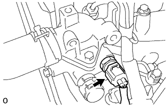 |
Connect the sensor connector.
| 10. INSTALL CRANKSHAFT POSITION SENSOR |
Apply a light coat of engine oil to the O-ring of the sensor.
Install the sensor with the bolt.
- Torque:
- 5.0 N*m{51 kgf*cm, 44 in.*lbf}
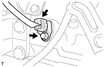 |
Connect the sensor connector.
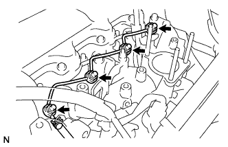
| 11. INSTALL INJECTION PUMP ASSEMBLY |
Install the injection pump to the timing gear case, and temporarily tighten the 2 nuts.
 |
Install the injection pump stay to the injection pump rear end, and temporarily tighten the 3 bolts.
Rotate the pump body to align the markings of the pump flange and timing gear case.
 |
Tighten the 2 nuts to install the injection pump.
- Torque:
- 21 N*m{210 kgf*cm, 15 ft.*lbf}
Tighten the 3 bolts to install the injection pump stay.
- Torque:
- 26 N*m{265 kgf*cm, 19 ft.*lbf}for injection pump stay to cylinder block
- 26 N*m{265 kgf*cm, 19 ft.*lbf}for injection pump stay to injection pump
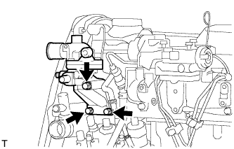
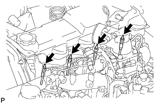
Connect the 3 fuel hoses.
 |
Connect the engine speed sensor connector.
Connect the spill control valve connector.
Connect the correction unit connector.
Connect the timing control valve connector.
Connect the fuel temperature sensor connector.
Connect the engine wire clamp.
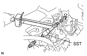
| 12. INSTALL INJECTION PUMP DRIVE PULLEY |
Using SST, install the injection pump drive pulley with the nut.
- SST
- 09213-14010(91651-60865)
09330-00021
- Torque:
- 64 N*m{650 kgf*cm, 47 ft.*lbf}
 |
| 13. INSTALL GLOW PLUG ASSEMBLY |
Using a 12 mm deep socket wrench, install the 4 glow plugs.
- Torque:
- 13 N*m{130 kgf*cm, 10 ft.*lbf}
 |
| 14. INSTALL NOZZLE HOLDER & NOZZLE SET |
Place 4 new injection nozzle seat gaskets and 4 injection nozzle seats into the injection nozzle holes of the cylinder head.
 |
Using SST, install the 4 nozzle holders and nozzle sets.
- SST
- 09268-64010(09268-64020)
- Torque:
- 64 N*m{650 kgf*cm, 47 ft.*lbf}
| 15. INSTALL NOZZLE LEAKAGE PIPE ASSEMBLY |
Install 4 new ring packing washers and the leakage pipe with the 4 nuts.
- Torque:
- 29.5 N*m{300 kgf*cm, 22 ft.*lbf}
 |
Connect the fuel hose to the leakage pipe.
| 16. INSTALL NO. 1 GLOW PLUG CONNECTOR |
Install the glow plug connector by uniformly tightening the 4 nuts.
- Torque:
- 1.0 N*m{10 kgf*cm, 9 in.*lbf}
Install the 4 screw grommets.
Connect the glow plug connector wire with the nut.
- Torque:
- 8.4 N*m{85 kgf*cm, 74 in.*lbf}
| 17. INSTALL INJECTION PIPE SET |
Connect the 2 lower pipe clamps onto the intake manifold.
 |
Install the 4 injection pipes.
- Torque:
- 25 N*m{250 kgf*cm, 18 ft.*lbf}
- NOTICE:
- Use the formula to calculate special torque values for situations where a union nut wrench is combined with a torque wrench (Toyota Fortuner RM000000UYX010X.html).
Secure the injection pipes with the 2 upper pipe clamps and 2 nuts.
- Torque:
- 5.0 N*m{51 kgf*cm, 44 in.*lbf}
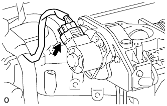
| 18. INSTALL VENTURI ASSEMBLY |
Place a new gasket and the venturi on the intake manifold.
Connect the throttle control motor connector.
 |
Connect the throttle open switch connector.
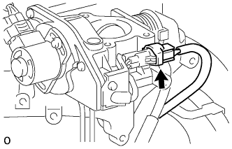 |
| 19. INSTALL OIL DIPSTICK GUIDE |
Apply clean engine oil to a new O-ring.
Install the O-ring to the guide.
Install the guide with the 2 bolts.
- Torque:
- 23.5 N*m{240 kgf*cm, 17 ft.*lbf}
- 39 N*m{398 kgf*cm, 29 ft.*lbf}
| 20. INSTALL OIL DIPSTICK SUB-ASSEMBLY |
Install the dipstick to the guide.
| 21. INSTALL INTAKE PIPE |
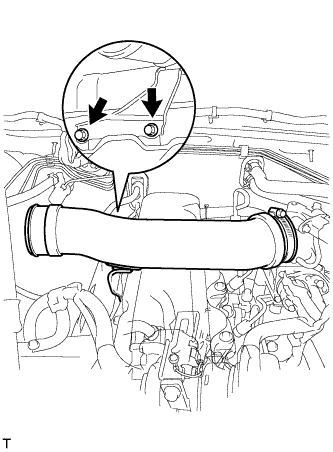 |
Install the intake pipe with the 2 bolts.
- Torque:
- 18 N*m{184 kgf*cm, 13 ft.*lbf}
Tighten the intake pipe clamp.
| 22. INSTALL GENERATOR ASSEMBLY |
Install the generator with the bolt.
- Torque:
- 75 N*m{765 kgf*cm, 55 ft.*lbf}
 |
Connect the vacuum oil outlet hose.
Install 2 new gaskets and the vacuum pump hose with the union bolt.
- Torque:
- 14 N*m{143 kgf*cm, 10 ft.*lbf}
 |
Install the vacuum pump oil inlet hose with 2 new gaskets and the union bolt.
- Torque:
- 14 N*m{143 kgf*cm, 10 ft.*lbf}
Attach the vacuum pump oil inlet hose to the cord clip.
Install the generator wire with the nut.
- Torque:
- 9.8 N*m{100 kgf*cm, 7 ft.*lbf}
 |
Attach the terminal cap.
Connect the generator connector.
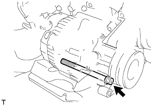
| 23. INSTALL COMPRESSOR MOUNTING BRACKET (w/ Air Conditioning System) |
Temporarily install the compressor mounting bracket with the 4 bolts.
Using several steps, uniformly install and tighten the 4 bolts.
- Torque:
- 85 N*m{870 kgf*cm, 63 ft.*lbf}
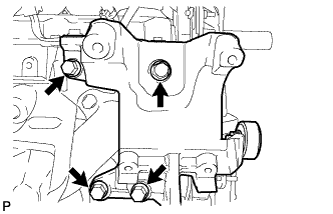 |
Temporarily install the spacer with the bolt.
 |
| 24. INSTALL FAN BELT ADJUSTING BAR (w/o Air Conditioning System) |
Install the fan belt adjusting bar with the 2 bolts.
- Torque:
- 45 N*m{460 kgf*cm, 33 ft.*lbf}
 |
Temporarily install the bolt.
 |
| 25. INSTALL ENGINE WIRE |
| 26. REMOVE ENGINE ON ENGINE STAND |
| 27. INSTALL ENGINE ASSEMBLY |
Attach a chain block and engine sling device to the engine hangers.
Slowly lower the engine into the engine compartment.
Install the engine mounting bracket with the 4 bolts.
- Torque:
- 49 N*m{500 kgf*cm, 36 ft.*lbf}
Remove the bolt and No. 2 engine hanger.
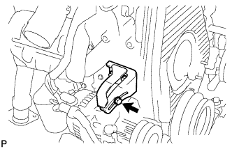
| 28. INSTALL VANE PUMP ASSEMBLY |
Temporarily install the vane pump assembly with the 2 bolts.
Install the pulley to the pump shaft.
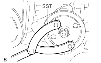 |
Using SST, stop the pulley rotation and torque the nut.
- SST
- 09960-10010(09962-01000,09963-01000)
- Torque:
- 43 N*m{440 kgf*cm, 32 ft.*lbf}
| 29. INSTALL COMPRESSOR AND MAGNET CLUTCH (w/ Air Conditioning System) |
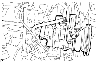 |
Install the compressor with the 4 bolts.
- Torque:
- 50 N*m{510 kgf*cm, 37 ft.*lbf}
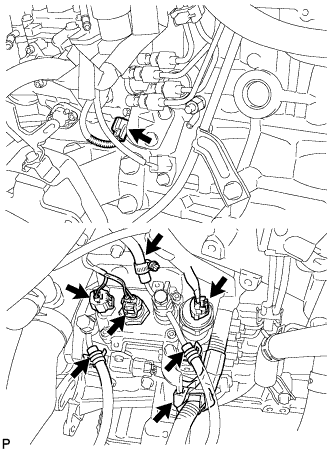
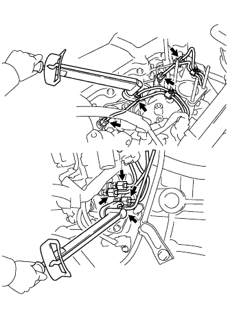
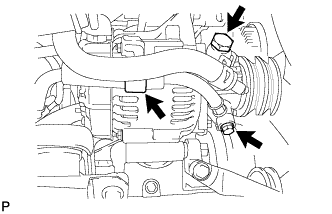
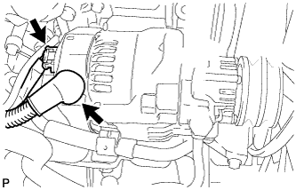
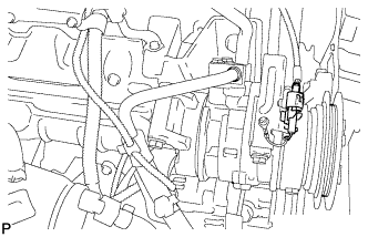
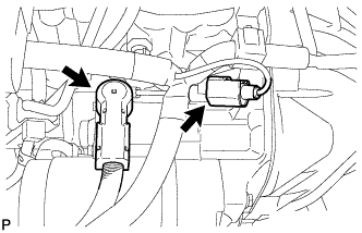
| 30. CONNECT HOSES AND CONNECTORS |
Connect the vacuum pump hose to the generator.
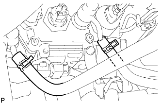
Connect the connectors as shown in the illustration.
 |
Connect the compressor connector.
 |
Connect the 2 water hoses.
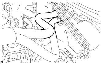 |
Install the water hose clamp with the bolt.
Connect the 2 fuel hoses.
 |
Install the ground cable with the bolt.
- Torque:
- 30 N*m{306 kgf*cm, 22 ft.*lbf}
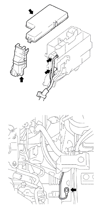 |
Connect the 2 engine room junction block connectors.
Install the engine room junction block wire with the nut.
- Torque:
- 13 N*m{133 kgf*cm, 10 ft.*lbf}
Install the engine room relay block cover (side).
Install the engine room relay block cover (upper).
| 31. INSTALL REAR END PLATE |
Install the rear end plate with the 2 bolts.
- Torque:
- 27 N*m{275 kgf*cm, 20 ft.*lbf}
| 32. INSTALL FLYWHEEL SUB-ASSEMBLY |
 |
Using SST, hold the crankshaft.
- SST
- 09213-54015(91651-60855)
09330-00021
Clean the bolts and bolt holes.
Apply adhesive to 2 or 3 threads of the bolts.
- Adhesive:
- Toyota Genuine Adhesive 1324, Three Bond 1324 or equivalent
 |
Install the flywheel on the crankshaft.
Install and uniformly tighten the 8 bolts in several steps, in the sequence shown in the illustration.
- Torque:
- 123 N*m{1,250 kgf*cm, 90 ft.*lbf}
- NOTICE:
- Do not start the engine for an hour after the installation.
 |
| 33. INSTALL CLUTCH DISC ASSEMBLY |
 |
Insert SST into the clutch disc. Then insert SST (together with the clutch disc) into the flywheel.
- SST
- 09301-00110
- NOTICE:
- Make sure not to insert the clutch disc facing the wrong direction.
| 34. INSTALL CLUTCH COVER ASSEMBLY |
Align the matchmarks on the clutch cover and flywheel.
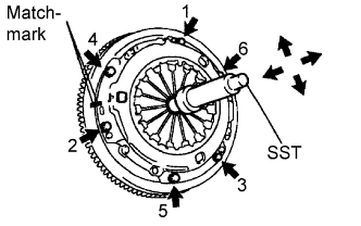 |
Loosely install the 6 bolts.
Tighten the 6 bolts as described below.
Determine the first bolt to be tightened by choosing the bolt closest to the knock pin.
Uniformly tighten the 6 bolts in diametrically opposite pairs relative to the position of the first bolt. Use the illustration as a reference.
- Torque:
- 19 N*m{195 kgf*cm, 14 ft.*lbf}
Lightly move SST up and down, and right and left.
- SST
- 09301-00110
Check that the disc is in the center, and then tighten the bolts.
| 35. INSTALL TRANSMISSION ASSEMBLY |
 |
Align the input shaft with the clutch disc and install the transmission to the engine.
Install the 4 bolts.
- Torque:
- 72 N*m{730 kgf*cm, 53 ft.*lbf}
| 36. INSTALL PROPELLER SHAFT ASSEMBLY |
for Front Side:
Install the propeller shaft (Toyota Fortuner RM000000ZYG008X.html).
for Rear Side:
Install the propeller shaft (Toyota Fortuner RM000000ZZ1008X.html).
| 37. INSTALL FRONT EXHAUST PIPE ASSEMBLY |
Install a new gasket to the front exhaust pipe.
- NOTICE:
- Do not reuse the gasket.
Temporarily install the pipe support and clamp to the front exhaust pipe with the bolt.
Install the front exhaust pipe to the exhaust manifold with 3 new nuts. Alternately tighten the nuts in several passes.
- Torque:
- 62 N*m{632 kgf*cm, 46 ft.*lbf}
- NOTICE:
- Do not reuse the 3 nuts.
Install the pipe support to the transmission with the 2 bolts.
- Torque:
- 71 N*m{724 kgf*cm, 52 ft.*lbf}
Tighten the pipe support's clamp with the bolt.
- Torque:
- 19 N*m{194 kgf*cm, 14 ft.*lbf}
Install the front fender seal LH with the 5 clips.
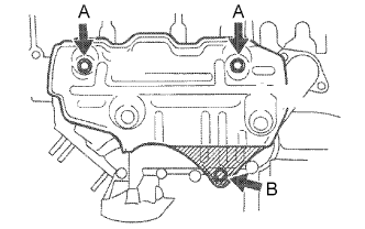
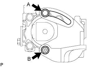
| 38. INSTALL NO. 1 EXHAUST MANIFOLD HEAT INSULATOR |
Install the heat insulator with the 3 bolts.
- Torque:
- 18 N*m{185 kgf*cm, 13 ft.*lbf}for bolt A
- 19 N*m{195 kgf*cm, 14 ft.*lbf}for bolt B
 |
| 39. INSTALL STARTER ASSEMBLY |
Install the starter with the 2 bolts and nut.
- Torque:
- 69 N*m{700 kgf*cm, 51 ft.*lbf}
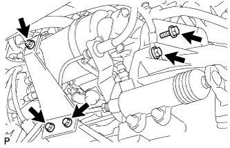 |
Install the stay with the 2 bolts.
- Torque:
- 37 N*m{377 kgf*cm, 27 ft.*lbf}
Install the nut to the stay.
- Torque:
- 12.3 N*m{125 kgf*cm, 9 ft.*lbf}
Connect the terminal 30 wire with the nut.
- Torque:
- 9.8 N*m{100 kgf*cm, 7 ft.*lbf}
Install the terminal cap.
 |
Connect the starter connector.
| 40. INSTALL RADIATOR ASSEMBLY |
Install the radiator with the 4 bolts.
- Torque:
- 12 N*m{122 kgf*cm, 9 ft.*lbf}
 |
| 41. INSTALL FAN & GENERATOR V BELT (w/ Air Conditioning System) |
Install the V belt.
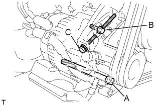 |
Tightening bolt C, adjust the deflection of the V belt (Toyota Fortuner RM000001KYZ001X_01_0001.html).
Tighten the bolts A and B.
- Torque:
- 75 N*m{765 kgf*cm, 55 ft.*lbf}for bolt A
- 18 N*m{185 kgf*cm, 13 ft.*lbf}for bolt B
Recheck the deflection of the V belt.
| 42. INSTALL FAN & GENERATOR V BELT (w/o Air Conditioning System) |
Install the V belt.
 |
Using a bar, adjust the tension of the V belt.
Tighten the bolts A and B.
- Torque:
- 75 N*m{765 kgf*cm, 55 ft.*lbf}for bolt A
- 18 N*m{185 kgf*cm, 13 ft.*lbf}for bolt B
Check the deflection of the V belt (Toyota Fortuner RM000001KYZ001X_01_0001.html).
| 43. INSTALL COOLER COMPRESSOR V BELT (w/ Air Conditioning System) |
Install the V belt.
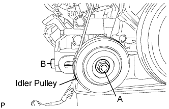 |
Tightening bolt B, adjust the deflection of the V belt (Toyota Fortuner RM000001KYZ001X_01_0001.html).
Tighten nut A.
- Torque:
- 39 N*m{400 kgf*cm, 29 ft.*lbf}
Recheck the deflection of the V belt.
| 44. INSTALL VANE PUMP V BELT |
Install the V belt.
 |
Using a bar, adjust the deflection of the V belt (Toyota Fortuner RM000001KYZ001X_01_0001.html).
Tighten bolt A and nut B.
- Torque:
- 48 N*m{489 kgf*cm, 35 ft.*lbf}for bolt A
- 64 N*m{635 kgf*cm, 47 ft.*lbf}for bolt B
Recheck the deflection of the V belt.
| 45. INSTALL FAN SHROUD |
Install the fan pulley to the water pump.
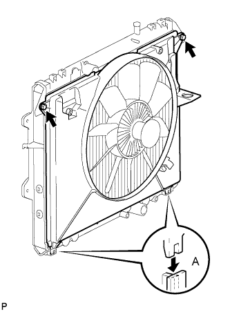 |
Install the shroud together with the coupling fan between the radiator and engine.
- NOTICE:
- Be careful not to damage the radiator core.
Install the fluid coupling fan to the fan pulley with the 4 nuts.
- HINT:
- Tighten the nuts as much as possible by hand.
Attach the shroud's claws to the radiator as shown in A in the illustration.
Install the shroud with the 2 bolts.
- Torque:
- 5.0 N*m{51 kgf*cm, 44 in.*lbf}
Install the fan and generator V belt, cooler compressor V belt and vane pump V belt (Toyota Fortuner RM00000122V002X.html).
Tighten the 4 nuts of the fluid coupling fan.
- Torque:
- 19 N*m{194 kgf*cm, 14 ft.*lbf}
Install the radiator reservoir with the bolt.
- Torque:
- 5.0 N*m{51 kgf*cm, 44 in.*lbf}
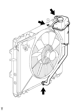 |
Connect the No. 1 and No. 2 water by-pass hoses to the tank upper and lower.
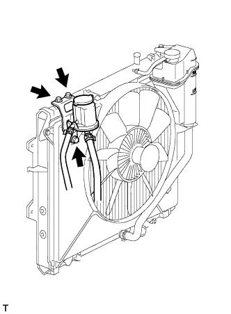
Install the oil reservoir with the 3 bolts.
- Torque:
- 5.0 N*m{51 kgf*cm, 44 in.*lbf}
 |
| 46. CONNECT RADIATOR HOSE OUTLET |
| 47. CONNECT RADIATOR HOSE INLET |
| 48. INSTALL AIR CLEANER ASSEMBLY |
Install the cleaner with the 2 bolts.
- Torque:
- 14 N*m{143 kgf*cm, 10 ft.*lbf}
Connect the connector to the IAT sensor.
Connect the hose clamp.
| 49. INSTALL BATTERY AND BATTERY TRAY |
| 50. INSTALL BATTERY BRACKET |
Install the battery bracket with the bolt.
- Torque:
- 5.0 N*m{51 kgf*cm, 44 in.*lbf}
| 51. INSTALL HOOD SUB-ASSEMBLY |
Install the hood with the 4 bolts.
- Torque:
- 13 N*m{133 kgf*cm, 10 ft.*lbf}
Connect the washer nozzle hose.
Adjust the hood.
| 52. ADD ENGINE OIL |
Add fresh engine oil.
- Standard capacity:
Item Specified Condition Drain and refill with oil filter change 7.2 liters (7.6 US qts, 6.3 Imp. qts) Drain and refill without oil filter change 6.7 liters (7.1 US qts, 5.9 Imp. qts) Dry fill 8.4 liters (8.9 US qts, 7.4 Imp. qts)
Install the oil filler cap.
| 53. ADD ENGINE COOLANT |
Tighten the radiator drain cock plug by hand.
Tighten the cylinder block drain cock plug.
- Torque:
- 57 N*m{581 kgf*cm, 42 ft.*lbf}
Fill the radiator with TOYOTA Super Long Life Coolant (SLLC) to the reservoir tank's FULL line.
- Standard capacity:
- 9.4 liters (9.9 US qts, 8.3 Imp. qts)
- HINT:
- TOYOTA vehicles are filled with TOYOTA SLLC at the factory. In order to avoid damage to the engine cooling system and other technical problems, only use TOYOTA SLLC or similar high quality ethylene glycol based non-silicate, non-amine, non-nitrite, non-borate coolant with long-life hybrid organic acid technology (coolant with long-life hybrid organic acid technology consists of a combination of low phosphates and organic acids).
- Please contact your TOYOTA dealer for further details.
- NOTICE:
- Never use water as a substitute for engine coolant.
 |
Press the inlet and outlet radiator hoses several times by hand, and then check the level of the coolant.
If the coolant level drops below the LOW line, add TOYOTA SLLC to the FULL line.
Install the radiator reservoir cap.
Using a wrench, install the vent plug.
- Torque:
- 2.0 N*m{20 kgf*cm, 18 in.*lbf}
 |
Bleed air from the cooling system.
Warm up the engine until the thermostat opens. While the thermostat is open, circulate the coolant for several minutes.
Maintain the engine speed at 2,500 to 3,000 rpm.
Press the inlet and outlet radiator hoses several times by hand to bleed air.
- CAUTION:
- When pressing the radiator hoses:
- Wear protective gloves.
- Be careful as the radiator hoses are hot.
- Keep your hands away from the radiator fan.
Stop the engine and wait until the coolant cools down to ambient temperature.
- CAUTION:
- Do not remove the radiator reservoir cap while the engine and radiator are still hot. Pressurized, hot engine coolant and steam may be released and cause serious burns.
After the coolant cools down, check that the coolant level is at the FULL line.
If the coolant level is below the LOW line, add TOYOTA SLLC to the FULL line.
|
| 54. TIGHTEN FUEL TANK CAP ASSEMBLY |
| 55. BLEED AIR FROM FUEL SYSTEM |
 |
Using the hand pump, bleed air from the fuel system until pumping becomes difficult.
| 56. CONNECT CABLE TO NEGATIVE BATTERY TERMINAL |
| 57. INSPECT FOR FUEL LEAK |
Check that there are no fuel leaks anywhere on the fuel system after performing maintenance.
- HINT:
- When checking for fuel leaks, make sure that there is pressure in the fuel line.
| 58. INSPECT FOR OIL LEAK |
Start the engine, and check that there are no oil leaks after performing maintenance.
| 59. INSPECT FOR COOLANT LEAK |
Check for engine coolant leaks (Toyota Fortuner RM000001443007X_01_0001.html).
| 60. INSPECT FOR EXHAUST GAS LEAK |
- HINT:
- If gas is leaking, tighten the areas necessary to stop the leak.
- Replace damaged parts as necessary.
| 61. INSPECT ENGINE IDLE SPEED |
Warm up the engine.
When using the intelligent tester:
Connect the intelligent tester to the DLC3.
Measure the idle speed.
- Standard idle speed:
- 720 to 820 rpm (A/C OFF)
750 to 850 rpm (A/C ON)
- HINT:
- Refer to the intelligent tester operator's manual for further details.
When not using the intelligent tester:
Using SST, connect the tachometer test probe to terminal 9 (TAC) of the DLC3.
- SST
- 09843-18040
Measure the idle speed.
- Standard idle speed:
- 720 to 820 rpm (A/C OFF)
750 to 850 rpm (A/C ON)
- NOTICE:
- Switch off all accessories.

| 62. INSPECT MAXIMUM ENGINE SPEED |
Start the engine.
Fully depress the accelerator pedal.
Measure the maximum speed.
- Maximum speed:
- 4,850 to 4,950 rpm
| 63. INSTALL NO. 2 ENGINE UNDER COVER |
Install the under cover with the 4 bolts.
- Torque:
- 28 N*m{286 kgf*cm, 21 ft.*lbf}
| 64. INSTALL NO. 1 ENGINE UNDER COVER |
Install the under cover with the 8 bolts.
- Torque:
- 28 N*m{286 kgf*cm, 21 ft.*lbf}