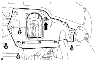
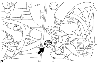
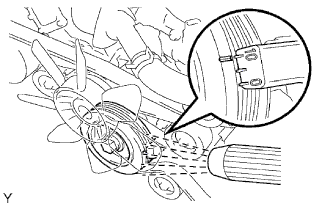
| 1. REMOVE FRONT FENDER SPLASH SHIELD SUB-ASSEMBLY LH |
-
Remove the 3 bolts and screw.
-
Turn the clip indicated by the arrow in the illustration to remove the fender splash shield.
| 2. REMOVE FRONT FENDER SPLASH SHIELD SUB-ASSEMBLY RH |
HINT:
Use the same procedures described for the LH side.
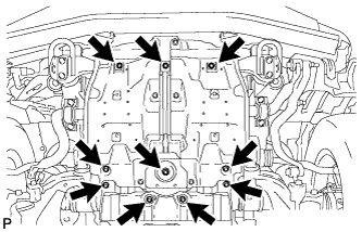
| 3. REMOVE NO. 1 ENGINE UNDER COVER SUB-ASSEMBLY |
-
Remove the 10 bolts and under cover.
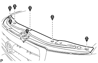
| 4. REMOVE UPPER RADIATOR SUPPORT SEAL |
-
Remove the 7 clips and radiator support seal.
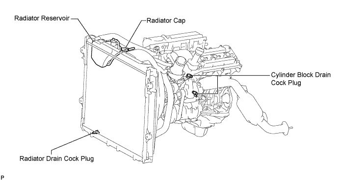
| 5. DRAIN ENGINE COOLANT |
CAUTION:
Do not remove the radiator cap while the engine and radiator are still hot. Pressurized, hot engine coolant and steam may be released and cause serious burns.
-
Loosen the radiator drain cock plug and 2 cylinder block drain cock plugs.
-
Remove the radiator cap. Then drain the coolant.
HINT:
Collect the coolant in a container and dispose of it according to the regulations in your area.
-
Tighten the 2 cylinder block drain cock plugs.
Torque:
13 N*m{ 133 kgf*cm , 10 ft.*lbf }
-
Tighten the radiator drain cock plug by hand.
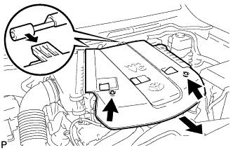
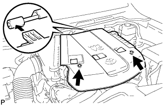
| 6. REMOVE V-BANK COVER |
-
Remove the 2 cap nuts and V-bank cover.
| 7. REMOVE COWL TOP VENTILATOR LOUVER SUB-ASSEMBLY |
-
Remove the cowl top ventilator louver .
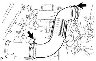
| 8. REMOVE NO. 2 AIR CLEANER HOSE |
-
Loosen the 2 hose clamps and remove the air cleaner hose.
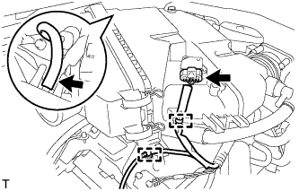
| 9. REMOVE AIR CLEANER ASSEMBLY |
-
Disconnect the No. 2 ventilation hose.
-
Detach the hose clamp.
-
Disconnect the vacuum hose.
-
Disconnect the MAF meter connector.
-
Using a clip remover, detach the 2 wire harness clamps.
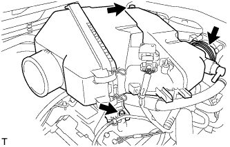
-
Loosen the hose clamp.
-
Remove the 2 bolts and air cleaner assembly.
| 10. REMOVE INTAKE AIR SURGE TANK |
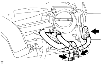
-
Disconnect the throttle body connector.
-
Disconnect the No. 4 water by-pass hose.
-
Disconnect the No. 5 water by-pass hose.
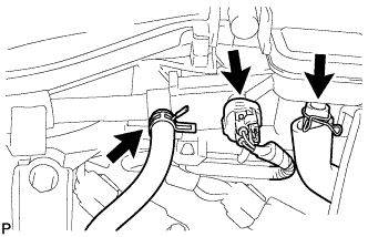
-
Disconnect the purge line hose.
-
Disconnect the purge VSV connector.
-
Disconnect the No. 1 ventilation hose.
-
Disconnect the vacuum switching valve (for ACIS) connector.
-
Using a clip remover, detach the 2 wire harness clamps.
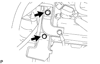
-
Remove the 2 bolts and throttle body bracket.
-
Using a clip remover, detach the wire harness clamp.
-
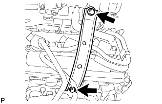
Remove the bolt and bracket from the No. 1 surge tank stay.
-
Remove the bolt and oil baffle plate.
-
Remove the 2 bolts and No. 1 surge tank stay.
-
for Manual Transmission:
-
Remove the nut.
-
-
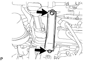
Remove the 2 bolts and No. 2 surge tank stay.
-
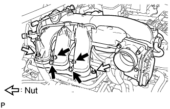
Remove the 2 nuts.
-
Using an 8 mm hexagon wrench, remove the 4 bolts. Then remove the intake air surge tank and gasket.
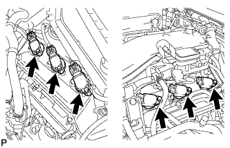
| 11. REMOVE IGNITION COIL ASSEMBLY |
-
Disconnect the 6 ignition coil connectors.
-
Remove the 6 bolts and 6 ignition coils.
| 12. REMOVE SPARK PLUG |
-
Remove the 6 spark plugs.
| 13. REMOVE CYLINDER HEAD COVER SUB-ASSEMBLY RH |
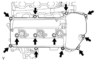
-
Remove the 10 bolts, 3 seal washers, 2 nuts, cylinder head cover and gasket.
| 14. REMOVE CYLINDER HEAD COVER SUB-ASSEMBLY LH |
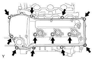
-
Remove the 10 bolts, 3 seal washers, 2 nuts, cylinder head cover and gasket.
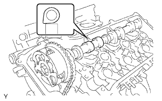
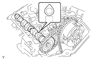
| 15. SET NO. 1 CYLINDER TO TDC/COMPRESSION |
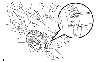
Turn the crankshaft pulley, and align its groove with the timing mark "0" of the timing chain cover.
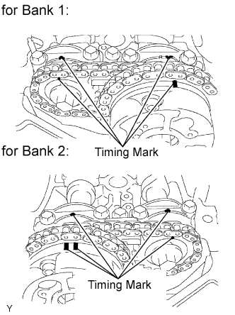
-
Check that the timing marks of the camshaft timing gears and sprockets are aligned with the timing marks of the bearing caps as shown in the illustration. If not, turn the crankshaft 1 complete revolution (360°) and align the timing marks as above.
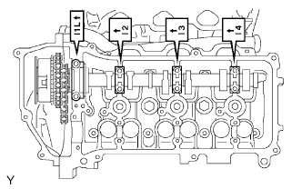
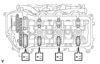
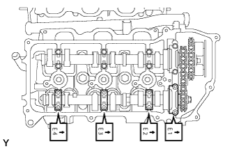
| 16. INSPECT VALVE CLEARANCE |
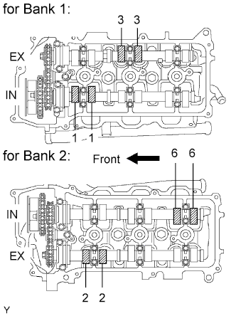
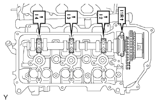
Check the valves indicated in the illustration.
-
Using a feeler gauge, measure the clearance between the valve lifter and camshaft.
Standard Valve Clearance (Cold):
Item Specified Condition Intake 0.15 to 0.25 mm (0.00591 to 0.00984 in.) Exhaust 0.29 to 0.39 mm (0.0114 to 0.0154 in.) -
Record the out-of-specification valve clearance measurements. They will be used later to determine the required replacement valve lifter.
-
-
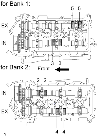
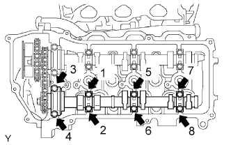
Turn the crankshaft 2/3 of a revolution (240°).
-
Check the valves indicated in the illustration.
-
Using a feeler gauge, measure the clearance between the valve lifter and camshaft.
Standard Valve Clearance (Cold):
Item Specified Condition Intake 0.15 to 0.25 mm (0.00591 to 0.00984 in.) Exhaust 0.29 to 0.39 mm (0.0114 to 0.0154 in.) -
Record the out-of-specification valve clearance measurements. They will be used later to determine the required replacement valve lifter.
-
-
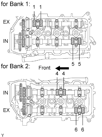
Turn the crankshaft 2/3 of a revolution (240°).
-
Check the valves indicated in the illustration.
-
Using a feeler gauge, measure the clearance between the valve lifter and camshaft.
Standard Valve Clearance (Cold):
Item Specified Condition Intake 0.15 to 0.25 mm (0.00591 to 0.00984 in.) Exhaust 0.29 to 0.39 mm (0.0114 to 0.0154 in.) -
Record the out-of-specification valve clearance measurements. They will be used later to determine the required replacement valve lifter.
-
| 17. ADJUST VALVE CLEARANCE |
-
Set the No. 1 cylinder to TDC/compression.
-
Turn the crankshaft pulley, and align the notch with the timing mark "0" of the timing chain cover.
-
Check that the timing marks of the camshaft timing gears and sprockets are aligned with the timing marks of the bearing caps as shown in the illustration. If not, turn the crankshaft 1 complete revolution (360°) and align the timing marks as above.
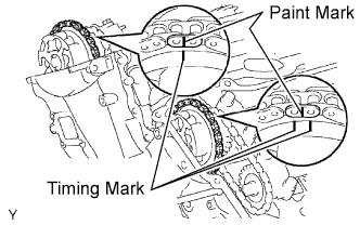
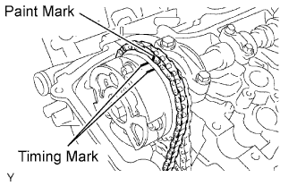
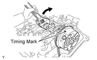
Place paint marks on the chain links that correspond with the timing marks of the camshaft timing gears.
-
Remove the No. 1 chain tensioner.
NOTICE:
- Never rotate the crankshaft with the No. 1 chain tensioner removed.
- When rotating the camshaft with the No. 1 chain removed, turn the crankshaft counterclockwise 40° from TDC first.
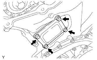
Remove the 4 bolts, timing chain cover plate and gasket.
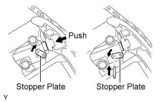
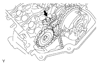
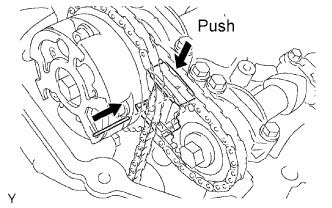
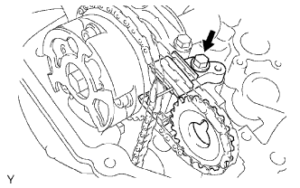
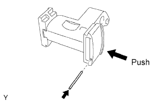
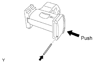
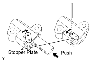
While rotating the stopper plate of the No. 1 chain tensioner clockwise, push in the plunger of the No. 1 chain tensioner as shown in the illustration.
-
While rotating the stopper plate of the tensioner counterclockwise downward, insert a bar of ?3.5 mm (0.138 in.) into the holes in the stopper plate and tensioner to fix the stopper plate in place.
-
Remove the 2 bolts and No. 1 chain tensioner.
-
Remove the No. 2 camshaft.
NOTICE:
As the thrust clearance of the camshaft is small, the camshaft must be kept level while it is being removed. If the camshaft is not kept level, the portion of the cylinder head which receives the shaft thrust may crack or be damaged, causing the camshaft to seize or break. To avoid this, the following steps should be carried out.
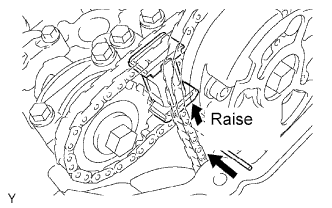
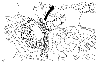
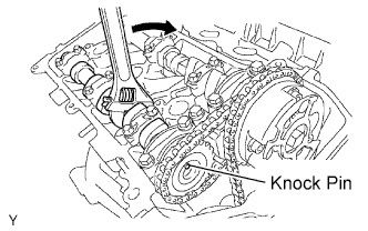
While raising the No. 2 chain tensioner, insert a pin of ?1.0 mm (0.0394 in.) into the hole to fix the tensioner in place.
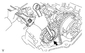
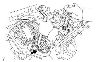
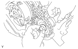
Hold the hexagonal portion of the No. 2 camshaft with a wrench, and remove the camshaft timing sprocket set bolt.
NOTICE:
Be careful not to damage the cylinder head and valve lifter with the wrench.
-
Separate the camshaft timing sprocket from the No. 2 camshaft.
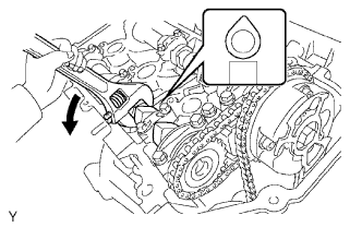
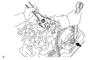
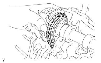
Rotate the camshaft counterclockwise using the wrench so that the cam lobes of the No. 1 cylinder face upward as shown in the illustration.
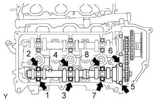
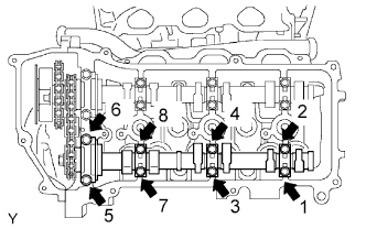
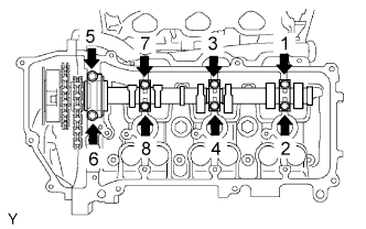
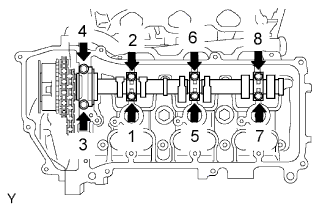
Uniformly loosen and remove the 8 bearing cap bolts in the sequence shown in the illustration.
-
Remove the 4 bearing caps and No. 2 camshaft.
Remove the No. 2 chain tensioner.
-
Remove the No. 2 chain tensioner bolt, No. 2 chain tensioner and camshaft timing sprocket.
-
-
Remove the No. 1 camshaft.
NOTICE:
As the thrust clearance of the camshaft is small, the camshaft must be kept level while it is being removed. If the camshaft is not kept level, the portion of the cylinder head which receives the shaft thrust may crack or be damaged, causing the camshaft to seize or break. To avoid this, the following steps should be carried out.
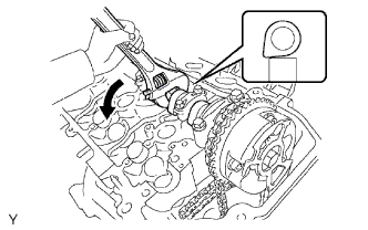
Hold the hexagonal portion of the No. 1 camshaft with a wrench, and loosen the camshaft timing gear set bolt.
NOTICE:
- Be careful not to damage the cylinder head and valve lifter with the wrench.
- Do not disassemble the camshaft timing gear.
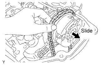
Slide the camshaft timing gear and separate the No. 1 chain from the camshaft timing gear.
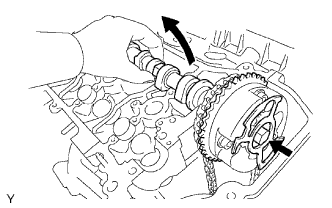
Rotate the No. 1 camshaft counterclockwise using a wrench so that the cam lobes of the No. 1 cylinder face downward as shown in the illustration.
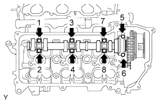
Uniformly loosen and remove the 8 bearing cap bolts in the sequence shown in the illustration.
-
Remove the 4 bearing caps.
Remove the camshaft timing gear set bolt with the No. 1 camshaft lifted up, and then remove the No. 1 camshaft and camshaft timing gear with the No. 2 chain.
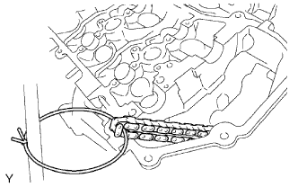
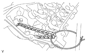
Tie the No. 1 chain with a string as shown in the illustration.
NOTICE:
Be careful not to drop anything inside the timing chain cover.
-
Remove the No. 4 camshaft.
NOTICE:
As the thrust clearance of the camshaft is small, the camshaft must be kept level while it is being removed. If the camshaft is not kept level, the portion of the cylinder head which receives the shaft thrust may crack or be damaged, causing the camshaft to seize or break. To avoid this, the following steps should be carried out.
While pushing down the No. 3 chain tensioner, insert a pin of ?1.0 mm (0.0394 in.) into the hole to fix the tensioner in place.
Hold the hexagonal portion of the No. 4 camshaft with a wrench, and remove the camshaft timing sprocket set bolt.
NOTICE:
Be careful not to damage the cylinder head and valve lifter with the wrench.
-
Separate the camshaft timing sprocket from the No. 4 camshaft.
Uniformly loosen and remove the 8 bearing cap bolts in the sequence shown in the illustration.
-
Remove the 4 bearing caps and No. 4 camshaft.
Remove the No. 3 chain tensioner.
-
Remove the No. 3 chain tensioner bolt, No. 3 chain tensioner and camshaft timing sprocket.
-
-
Remove the No. 3 camshaft.
NOTICE:
As the thrust clearance of the camshaft is small, the camshaft must be kept level while it is being removed. If the camshaft is not kept level, the portion of the cylinder head which receives the shaft thrust may crack or be damaged, causing the camshaft to seize or break. To avoid this, the following steps should be carried out.
Using several steps, loosen and remove the 8 bearing cap bolts uniformly in the sequence shown in the illustration.
-
Remove the 4 bearing caps.
Hold the No. 1 chain, and remove the No. 3 camshaft with camshaft timing gear and No. 2 chain.
Tie the No. 1 chain with a string as shown in the illustration.
NOTICE:
Be careful not to drop anything inside the timing chain cover.
-
Remove the 24 valve lifters from the cylinder head LH and RH.
Determine the size of the valve lifter to be installed according to the following formulas or charts.
-
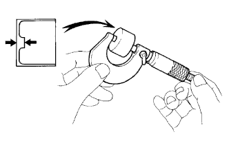
Using a micrometer, measure the thickness of the removed lifter.
-
Calculate the thickness of a new lifter so that the valve clearance comes within the specified value.
T:
Thickness of removed lifter
A:
Measured valve clearance
N:
Thickness of new lifter
Intake:
N = T + (A - 0.20 mm (0.00787 in.))
Exhaust:
N = T + (A - 0.34 mm (0.0131 in.))
-
Select a new lifter with a thickness as close as possible to the calculated value.
HINT:
Lifters are available in 35 sizes in increments of 0.020 mm (0.000787 in.), from 5.060 mm (0.1992 in.) to 5.740 mm (0.2260 in.).
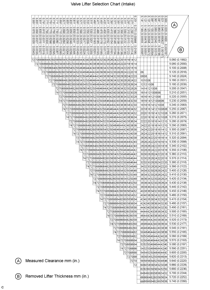
Intake valve clearance (Cold):
0.15 to 0.25 mm (0.00591 to 0.00984 in.) EXAMPLE: The 5.250 mm (0.2067 in.) lifter is installed, and the measured clearance is 0.400 mm (0.0157 in.). Replace the 5.250 mm (0.2067 in.) lifter with a No. 46 lifter.
New Lifter Thickness:
Lifter No. Thickness Lifter No. Thickness Lifter No. Thickness 06 5.060 mm (0.1992 in.) 30 5.300 mm (0.2087 in.) 54 5.540 mm (0.2181 in.) 08 5.080 mm (0.2000 in.) 32 5.320 mm (0.2094 in.) 56 5.560 mm (0.2189 in.) 10 5.100 mm (0.2008 in.) 34 5.340 mm (0.2102 in.) 58 5.580 mm (0.2197 in.) 12 5.120 mm (0.2016 in.) 36 5.360 mm (0.2110 in.) 60 5.600 mm (0.2205 in.) 14 5.140 mm (0.2024 in.) 38 5.380 mm (0.2118 in.) 62 5.620 mm (0.2213 in.) 16 5.160 mm (0.2031 in.) 40 5.400 mm (0.2126 in.) 64 5.640 mm (0.2220 in.) 18 5.180 mm (0.2039 in.) 42 5.420 mm (0.2134 in.) 66 5.660 mm (0.2228 in.) 20 5.200 mm (0.2047 in.) 44 5.440 mm (0.2142 in.) 68 5.680 mm (0.2236 in.) 22 5.220 mm (0.2055 in.) 46 5.460 mm (0.2150 in.) 70 5.700 mm (0.2244 in.) 24 5.240 mm (0.2063 in.) 48 5.480 mm (0.2157 in.) 72 5.720 mm (0.2252 in.) 26 5.260 mm (0.2071 in.) 50 5.500 mm (0.2165 in.) 74 5.740 mm (0.2260 in.) 28 5.280 mm (0.2079 in.) 52 5.520 mm (0.2173 in.) - - 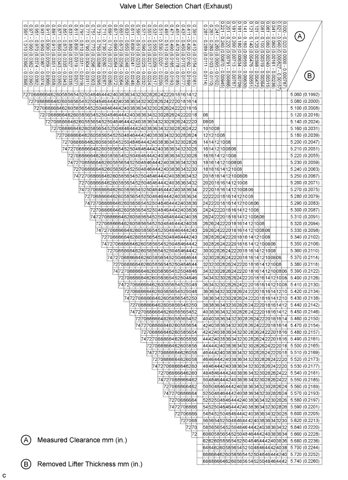
Exhaust valve clearance (Cold):
0.29 to 0.39 mm (0.0114 to 0.0154 in.) EXAMPLE: The 5.340 mm (0.210 in.) lifter is installed, and the measured clearance is 0.480 mm (0.0189 in.). Replace the 5.340 mm (0.210 in.) lifter with a No. 48 lifter.
New Lifter Thickness:
Lifter No. Thickness Lifter No. Thickness Lifter No. Thickness 06 5.060 mm (0.1992 in.) 30 5.300 mm (0.2087 in.) 54 5.540 mm (0.2181 in.) 08 5.080 mm (0.2000 in.) 32 5.320 mm (0.2094 in.) 56 5.560 mm (0.2189 in.) 10 5.100 mm (0.2008 in.) 34 5.340 mm (0.2102 in.) 58 5.580 mm (0.2197 in.) 12 5.120 mm (0.2016 in.) 36 5.360 mm (0.2110 in.) 60 5.600 mm (0.2205 in.) 14 5.140 mm (0.2024 in.) 38 5.380 mm (0.2118 in.) 62 5.620 mm (0.2213 in.) 16 5.160 mm (0.2031 in.) 40 5.400 mm (0.2126 in.) 64 5.640 mm (0.2220 in.) 18 5.180 mm (0.2039 in.) 42 5.420 mm (0.2134 in.) 66 5.660 mm (0.2228 in.) 20 5.200 mm (0.2047 in.) 44 5.440 mm (0.2142 in.) 68 5.680 mm (0.2236 in.) 22 5.220 mm (0.2051 in.) 46 5.460 mm (0.2150 in.) 70 5.700 mm (0.2244 in.) 24 5.240 mm (0.2063 in.) 48 5.480 mm (0.2157 in.) 72 5.720 mm (0.2252 in.) 26 5.260 mm (0.2071 in.) 50 5.500 mm (0.2165 in.) 74 5.740 mm (0.2260 in.) 28 5.280 mm (0.2079 in.) 52 5.520 mm (0.2173 in.) - -
-
-
Install the No. 3 camshaft.
NOTICE:
As the thrust clearance of the camshaft is small, the camshaft must be kept level while it is being installed. If the camshaft is not kept level, the portion of the cylinder head which receives the shaft thrust may crack or be damaged, causing the camshaft to seize or break. To avoid this, the following steps should be carried out.
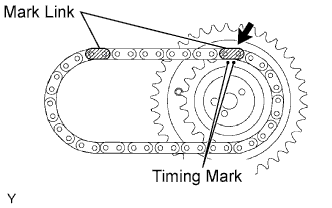
Align the mark link (yellow) with the timing mark (2-dot mark) of the camshaft timing gear shown in the illustration.
-
Apply a light coat of engine oil to the thrust portions and journals of the No. 3 camshaft.
Temporarily put the No. 1 chain on the No. 2 chain of the camshaft timing gear.
Set the No. 3 camshaft onto the cylinder head LH with the cam lobes of the No. 2 cylinder facing downward as shown in the illustration.
-
Apply a light coat of engine oil to the 4 bearing caps.
Set the 4 bearing caps in their proper locations.
-
Apply a light coat of engine oil to the threads of the 8 bearing cap bolts.
Uniformly install the 8 bearing cap bolts in several steps in the order shown in the illustration.
Torque:
for 10 mm head bolt:
9.0 N*m{ 92 kgf*cm , 80 in.*lbf }
for 12 mm head bolt:
24 N*m{ 245 kgf*cm , 18 ft.*lbf }
Set the paint mark of the No. 1 chain between the timing marks of the camshaft timing gear.
-
Install the No. 3 chain tensioner.
While pushing in the tensioner, insert a pin of ?1.0 mm (0.0394 in.) into the hole to fix the tensioner in place.
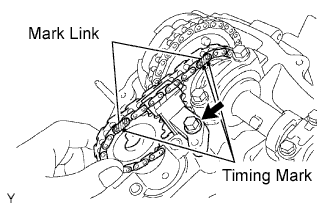
Temporarily install the camshaft timing sprocket and No. 3 chain tensioner with the bolt and align the mark links (yellow) with the timing marks (1-dot mark and 2-dot mark) of the camshaft timing gear and sprocket.
-
Tighten the No. 3 chain tensioner bolt.
Torque:
21 N*m{ 214 kgf*cm , 15 ft.*lbf }
-
Install the No. 4 camshaft.
NOTICE:
As the thrust clearance of the camshaft is small, the camshaft must be kept level while it is being installed. If the camshaft is not kept level, the portion of the cylinder head which receives the shaft thrust may crack or be damaged, causing the camshaft to seize or break. To avoid this, the following steps should be carried out.
-
Apply a light coat of engine oil to the thrust portions and journals of the No. 4 camshaft.
-
Apply a light coat of engine oil to the threads and under the head of the camshaft timing sprocket set bolt.
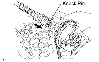
Align the knock pin hole on the camshaft timing sprocket with the knock pin of the No. 4 camshaft, and insert the No. 4 camshaft into the camshaft timing sprocket.
-
Temporarily install the camshaft timing sprocket set bolt.
Set the 4 bearing caps in their proper locations.
-
Apply a light coat of engine oil to the threads and under the heads of the 8 bearing cap bolts.
Uniformly install the 8 bearing cap bolts in several steps in the order shown in the illustration.
Torque:
for 10 mm head bolt:
9.0 N*m{ 92 kgf*cm , 80 in.*lbf }
for 12 mm head bolt:
24 N*m{ 245 kgf*cm , 18 ft.*lbf }
-
Hold the hexagonal portion of the No. 4 camshaft with a wrench, and tighten the camshaft timing sprocket set bolt.
Torque:
100 N*m{ 1020 kgf*cm , 74 ft.*lbf }
-
Remove the pin from the No. 3 chain tensioner.
-
-
Install the No. 1 camshaft.
NOTICE:
As the thrust clearance of the camshaft is small, the camshaft must be kept level while it is being installed. If the camshaft is not kept level, the portion of the cylinder head which receives the shaft thrust may crack or be damaged, causing the camshaft to seize or break. To avoid this, the following steps should be carried out.
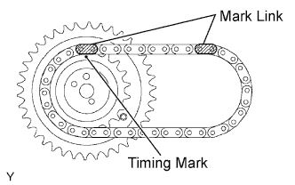
Align the mark link (yellow) with the timing mark (1-dot mark) of the camshaft timing gear as shown in the illustration.
-
Apply a light amount of engine oil to the thrust portions and journals of the camshaft.
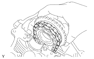
Temporarily put the No. 1 chain on the No. 2 chain of the camshaft timing gear.
Align the knock pin hole of the camshaft timing gear with the knock pin of the No. 1 camshaft, and insert the No. 1 camshaft into the camshaft timing gear.
-
Apply a light coat of engine oil to the threads and under the head of the camshaft timing gear set bolt.
-
Temporarily install the camshaft timing gear set bolt.
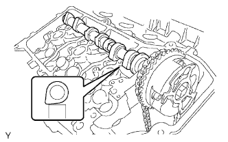
Set the No. 1 camshaft onto the cylinder head RH with the cam lobes of the No. 1 cylinder facing downward as shown in the illustration.
-
Apply a light coat of engine oil to the 4 bearing caps.
Set the 4 bearing caps in their proper locations.
-
Apply a light coat of engine oil to the threads and under the heads of the 8 bearing cap bolts.
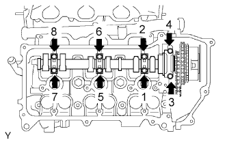
Uniformly install the 8 bearing cap bolts in several steps in the order shown in the illustration.
Torque:
for 10 mm head bolt:
9.0 N*m{ 92 kgf*cm , 80 in.*lbf }
for 12 mm head bolt:
24 N*m{ 245 kgf*cm , 18 ft.*lbf }
Rotate the No. 1 camshaft clockwise using the hexagonal portion of the No. 1 camshaft so that the timing mark of the camshaft timing gear is aligned with the timing mark of the camshaft bearing cap.
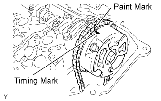
Align the paint mark of the No. 1 chain with the timing mark of the camshaft timing gear.
-
Hold the hexagonal portion of the No. 1 camshaft with a wrench, and tighten the camshaft timing gear set bolt.
Torque:
100 N*m{ 1020 kgf*cm , 74 ft.*lbf }
-
Install the No. 2 chain tensioner.
While pushing in the tensioner, insert a pin of ?1.0 mm (0.0394 in.) into the hole to fix the tensioner in place.
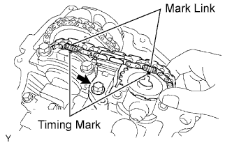
Temporarily install the camshaft timing sprocket and No. 2 chain tensioner with the bolt and align the mark links (yellow) with the timing marks (1-dot mark and 2-dot mark) of the camshaft timing gear and sprocket.
-
Tighten the No. 2 chain tensioner bolt.
Torque:
21 N*m{ 214 kgf*cm , 15 ft.*lbf }
-
Install the No. 2 camshaft.
NOTICE:
As the thrust clearance of the camshaft is small, the camshaft must be kept level while it is being installed. If the camshaft is not kept level, the portion of the cylinder head which receives the shaft thrust may crack or be damaged, causing the camshaft to seize or break. To avoid this, the following steps should be carried out.
-
Apply a light coat of engine oil to the thrust portions and journals of the No. 2 camshaft.
Set the No. 2 camshaft onto the cylinder head RH with the cam lobes of the No. 1 cylinder facing upward as shown in the illustration.
-
Apply a light coat of engine oil to the 4 bearing caps.
Set the 4 bearing caps in their proper locations.
-
Apply a light coat of engine oil to the threads and under the heads of the 8 bearing cap bolts.

Uniformly install the 8 bearing cap bolts in several steps in the order shown in the illustration.
Torque:
for 10 mm head bolt:
9.0 N*m{ 92 kgf*cm , 80 in.*lbf }
for 12 mm head bolt:
24 N*m{ 245 kgf*cm , 18 ft.*lbf }
Rotate the No. 2 camshaft clockwise using a wrench so that the knock pin of the No. 2 camshaft is aligned with the knock pin hole of the camshaft timing sprocket.
-
Apply a light coat of engine oil to the threads and under the head of the camshaft timing sprocket set bolt.
-
Hold the hexagonal portion of the No. 2 camshaft with a wrench, and install the camshaft timing sprocket set bolt.
Torque:
100 N*m{ 1020 kgf*cm , 74 ft.*lbf }
-
Remove the pin from the No. 2 chain tensioner.
-
-
Install the No. 1 chain tensioner.
While turning the stopper plate of the tensioner clockwise, push in the plunger of the tensioner as shown in the illustration.
-
While turning the stopper plate of the tensioner counterclockwise, insert a bar of ?3.5 mm (0.138 in.) into the holes on the stopper plate and tensioner to fix the stopper plate in place.
-
Apply a light coat of engine oil to the threads and under the heads of the 2 No. 1 chain tensioner bolts.
-
Install the No. 1 chain tensioner with the 2 bolts.
Torque:
10 N*m{ 102 kgf*cm , 7 ft.*lbf }
-
Remove the bar from the chain tensioner.
-
Install a new gasket and the timing chain cover plate with the 4 bolts.
Torque:
9.0 N*m{ 92 kgf*cm , 80 in.*lbf }
-
Turn the crankshaft pulley 2 complete revolutions slowly, and align the notch with the timing mark "0" of the timing chain cover.
-
Check that the timing marks of the camshaft timing gears and sprockets are aligned with the timing marks of the bearing caps as shown in the illustration.
| 18. INSTALL CYLINDER HEAD COVER SUB-ASSEMBLY LH |
-
Remove any old packing (FIPG) material and be careful not to drop any oil on the contact surfaces of the cylinder head, timing chain cover and cylinder head cover.
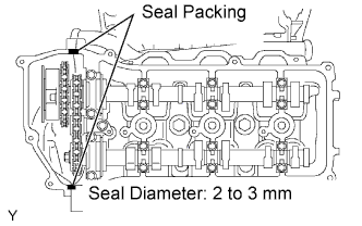
Apply seal packing as shown in the illustration.
Seal packing:
Toyota Genuine Seal Packing Black, Three Bond 1207B or equivalent
Standard seal diameter:
2 to 3 mm (0.0787 to 0.118 in.)
NOTICE:
- Remove any oil from the contact surface.
- Install the head cover within 3 minutes after applying seal packing.
- Do not start the engine for at least 2 hours after the installation.
-
Install a new gasket to the cylinder head cover.
-
Install the seal washers to the bolts.
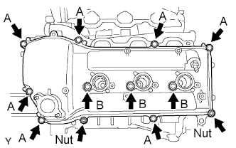
Temporarily install the cylinder head cover with the 10 bolts and 2 nuts. Tighten the bolts and nuts uniformly in several steps.
Torque:
for bolt A:
10 N*m{ 102 kgf*cm , 7 ft.*lbf }
for bolt B and nut:
9.0 N*m{ 92 kgf*cm , 80 in.*lbf }
| 19. INSTALL CYLINDER HEAD COVER SUB-ASSEMBLY RH |
-
Remove any old packing (FIPG) material and be careful not to drop any oil on the contact surfaces of the cylinder head, timing chain cover and cylinder head cover.
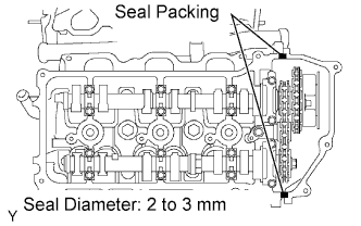
Apply seal packing as shown in the illustration.
Seal packing:
Toyota Genuine Seal Packing Black, Three Bond 1207B or equivalent
Standard seal diameter:
2 to 3 mm (0.0787 to 0.118 in.)
NOTICE:
- Remove any oil from the contact surface.
- Install the head cover within 3 minutes after applying seal packing.
- Do not start the engine for at least 2 hours after the installation.
-
Install a new gasket to the cylinder head cover.
-
Install the seal washers to the bolts.
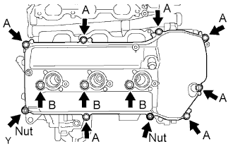
Temporarily install the cylinder head cover with the 10 bolts and 2 nuts. Tighten the bolts and nuts uniformly in several steps.
Torque:
for bolt A:
10 N*m{ 102 kgf*cm , 7 ft.*lbf }
for bolt B and nut:
9.0 N*m{ 92 kgf*cm , 80 in.*lbf }
| 20. INSTALL SPARK PLUG |
-
Install the 6 spark plugs.
Torque:
20 N*m{ 204 kgf*cm , 15 ft.*lbf }
| 21. INSTALL IGNITION COIL ASSEMBLY |
-
Install the 6 ignition coils with the 6 bolts.
Torque:
9.0 N*m{ 92 kgf*cm , 80 in.*lbf }
-
Connect the 6 ignition coil connectors.
| 22. INSTALL INTAKE AIR SURGE TANK |
NOTICE:
Do not apply oil to the bolts and nuts listed below: :
| Oil Application Prohibited Bolt/Nut |
| Bolt for surge tank and intake manifold |
| Nut for surge tank and intake manifold |
-
Install a new gasket to the intake air surge tank.
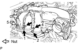
Using an 8 mm hexagon wrench, install the intake air surge tank with the 4 bolts and 2 nuts in the order shown in the illustration.
Torque:
28 N*m{ 286 kgf*cm , 21 ft.*lbf }
-
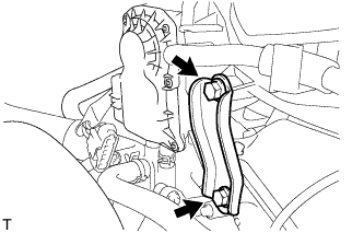
Install the No. 2 surge tank stay with the 2 bolts.
Torque:
21 N*m{ 214 kgf*cm , 15 ft.*lbf }
-
for Manual Transmission:
-
Install the bracket to the No. 2 surge tank stay with the nut.
Torque:
20 N*m{ 204 kgf*cm , 15 ft.*lbf }
-
-
Install the No. 1 surge tank stay with the 2 bolts.
Torque:
21 N*m{ 214 kgf*cm , 15 ft.*lbf }
-
Install the oil baffle plate with the bolt.
Torque:
9.0 N*m{ 92 kgf*cm , 80 in.*lbf }
-
Install the bracket to the No. 1 surge tank stay with the bolt.
Torque:
8.0 N*m{ 82 kgf*cm , 71 in.*lbf }
-
Attach the wire harness clamp.
-
Install the throttle body bracket with the 2 bolts.
Torque:
21 N*m{ 214 kgf*cm , 15 ft.*lbf }
-
Connect the vacuum switching valve (for ACIS) connector.
-
Attach the 2 wire harness clamps.
-
Connect the No. 1 ventilation hose.
-
Connect the purge VSV connector.
-
Connect the purge line hose.
HINT:
Connect the hose so that the direction of the hose clamp is as indicated in the illustration.
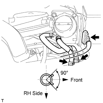
Connect the No. 4 and No. 5 water by-pass hose.
HINT:
Connect the hoses so that the direction of the hose clamps is as shown in the illustration.
-
Connect the throttle body connector.
| 23. INSTALL AIR CLEANER ASSEMBLY |
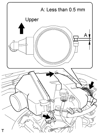
Install the air cleaner assembly with the 2 bolts.
Torque:
8.0 N*m{ 82 kgf*cm , 71 in.*lbf }
-
Tighten the hose clamp.
HINT:
Tighten the hose clamp until it reaches the specified protrusion height labeled A shown in the illustration.
Standard protrusion height:
Less than 0.5 mm (0.0197 in.)
-
Connect the MAF meter connector.
-
Attach the 2 wire harness clamps.
-
Connect the vacuum hose.
-
Attach the hose clamp.
-
Connect the No. 2 ventilation hose.
| 24. INSTALL NO. 2 AIR CLEANER HOSE |
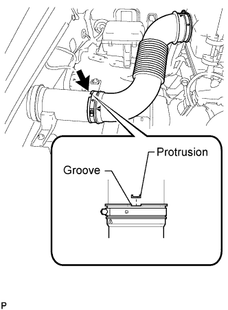
Align the protrusion of the pre-cleaner with the groove of the No. 2 air cleaner hose as shown in the illustration.
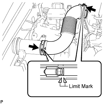
Tighten the 2 hose clamps.
Torque:
4.0 N*m{ 41 kgf*cm , 35 in.*lbf }
HINT:
Tighten the clamp until the end of the clamp band is within both limit marks.
| 25. INSTALL COWL TOP VENTILATOR LOUVER SUB-ASSEMBLY |
-
Install the cowl top ventilator louver .
| 26. ADD ENGINE COOLANT |
-
Add engine coolant.
Standard Capacity:
Item Specified condition for Automatic transmission w/o Rear Heater 11.2 liters (11.8 US qts, 9.9 Imp. qts) w/ Rear Heater 14.4 liters (15.2 US qts, 12.7 Imp. qts) for Manual transmission w/o Rear Heater 12.0 liters (12.7 US qts, 10.6 Imp. qts) w/ Rear Heater 14.6 liters (15.4 US qts, 12.8 Imp. qts) NOTICE:
Do not substitute plain water for engine coolant.
HINT:
TOYOTA vehicles are filled with TOYOTA SLLC at the factory. In order to avoid damage to the engine cooling system and other technical problems, only use TOYOTA SLLC or similar high quality ethylene glycol based non-silicate, non-amine, non-nitrite, non-borate coolant with long-life hybrid organic acid technology (coolant with long-life hybrid organic acid technology consists of a combination of low phosphates and organic acids).
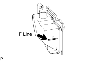
Slowly pour coolant into the radiator reservoir until it reaches the F line.
-
Install the reservoir cap.
-
Press the No. 1 and No. 2 radiator hoses several times by hand, and then check the coolant level. If the coolant level is low, add coolant.
-
Install the radiator cap.
-
Set the air conditioning as follows while warming up the engine.
Item Condition Fan speed Any setting except off Temperature Toward WARM Air conditioning switch Off
-
Start the engine and warm it up until the thermostat opens.
HINT:
The thermostat opening timing can be confirmed by pressing the No. 2 radiator hose by hand, and checking when the engine coolant starts to flow inside the hose.
-
Maintain the engine speed at 2000 to 2500 rpm.
NOTICE:
- Make sure that the radiator reservoir still has some coolant in it.
- Pay attention to the needle of the water temperature meter. Make sure that the needle does not show an abnormally high temperature.
- If there is not enough coolant, the engine may burn out or overheat.
- Immediately after starting the engine, if the radiator reservoir does not have any coolant, perform the following: 1) stop the engine, 2) wait until the coolant has cooled down, and 3) add coolant until the coolant is filled to the F line.
- Run the engine at 2000 rpm until the coolant level has stabilized.
-
Press the No. 1 and No. 2 radiator hoses several times by hand to bleed air.
CAUTION:
- Wear protective gloves. Heat areas on the parts may injure your hands.
- Be careful as the radiator hoses are hot.
- Keep your hands away from the fan.
-
Stop the engine, and wait until the engine coolant cools down to ambient temperature.
CAUTION:
Do not remove the radiator cap while the engine and radiator are still hot. Pressurized, hot engine coolant and steam may be released and cause serious burns.
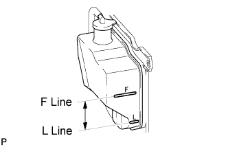
Check that the coolant level is between the F and L lines. If the coolant level is below the L line, repeat all of the procedures above. If the coolant level is above the F line, drain coolant so that the coolant level is between the F and L lines.
| 27. INSPECT FOR COOLANT LEAK |
CAUTION:
Do not remove the radiator cap while the engine and radiator are still hot. Pressurized, hot engine coolant and steam may be released and cause serious burns.
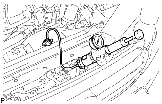
Fill the radiator with coolant and attach a radiator cap tester.
-
Warm up the engine.
-
Using the radiator cap tester, increase the pressure inside the radiator to 123 kPa (1.3 kgf/cm2, 18 psi), and check that the pressure does not drop. If the pressure drops, check the hoses, radiator and water pump for leaks. If no external leaks are found, check the heater core, cylinder block and head.
| 28. INSTALL UPPER RADIATOR SEAL |
-
Install the radiator support seal with the 7 clips.
| 29. INSTALL V-BANK COVER |
Install the V-bank cover with the 2 cap nuts.
Torque:
7.5 N*m{ 76 kgf*cm , 66 in.*lbf }
| 30. INSTALL NO. 1 ENGINE UNDER COVER SUB-ASSEMBLY |
-
Install the under cover with the 10 bolts.
| 31. INSTALL FRONT FENDER SPLASH SHIELD SUB-ASSEMBLY RH |
HINT:
Use the same procedures described for the LH side.
| 32. INSTALL FRONT FENDER SPLASH SHIELD SUB-ASSEMBLY LH |
-
Push in the clip indicated by the arrow in the illustration to install the fender splash shield.
-
Install the 3 bolts and screw.
| 33. INSPECT IGNITION TIMING |
NOTICE:
- Turn all electrical systems off.
- Perform the inspection when the cooling fan motor is turned off.
-
Warm up the engine.
-
When using the intelligent tester:
-
Connect the intelligent tester to the DLC3.
-
Enter the following menus: Powertrain / Engine and ECT / Data List / All Data / IGN Advance.
-
Inspect the ignition timing during idling.
Standard ignition timing:
8 to 12° BTDC @ idling (transmission in neutral position and A/C switch off)
-
Check that the ignition timing advances immediately when the engine speed is increased.
-
-
When not using the intelligent tester:
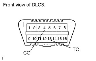
Using SST, connect terminals 13 (TC) and 4 (CG) of the DLC3.
SST
09843-18040
NOTICE:
Be sure not to improperly connect the terminals. This may damage the engine.
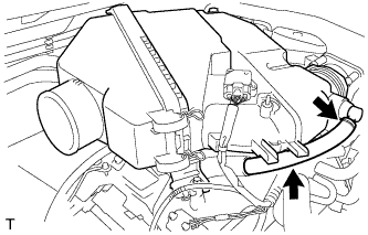
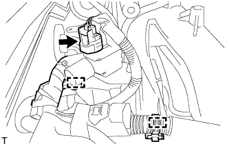
-
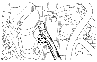
Remove the air cleaner cap.
Pull out the wire harness shown in the illustration.
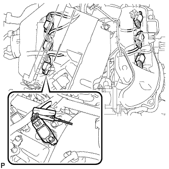
-
Connect the tester probe of a timing light to the wire of the ignition coil connector for the No. 1 cylinder.
NOTICE:
- Use a timing light that detects primary signals.
- After checking, be sure to wrap the wire harness with tape.
Inspect the ignition timing during idling.
Standard ignition timing:
8 to 12° BTDC @ idling (transmission in neutral position and A/C switch off)
-
Remove SST from the DLC3.
-
Inspect the ignition timing during idling.
Standard ignition timing:
7 to 24° BTDC @ idling (transmission in neutral position and A/C switch off)
-
Disconnect the timing light from the engine.
-
Install the air cleaner cap.