Fuel Injector Circuit 1GR-FE
DESCRIPTION
WIRING DIAGRAM
INSPECTION PROCEDURE
CHECK FUEL INJECTOR ASSEMBLY (POWER SOURCE)
INSPECT FUEL INJECTOR ASSEMBLY
CHECK HARNESS AND CONNECTOR (FUEL INJECTOR ASSEMBLY - ECM)
INSPECT FUSE (INJ, IG2 MAIN)
INSPECT INTEGRATION NO.1 RELAY (IG2)
SFI system - Fuel Injector Circuit
Description
The fuel injectors are located on the intake manifold. They inject fuel into the cylinders based on the signals from the ECM.
Wiring diagram
Inspection procedure
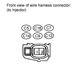
| 1.CHECK FUEL INJECTOR ASSEMBLY (POWER SOURCE) |
-
Disconnect the fuel injector connector.
-
Measure the voltage according to the value(s) in the table below.
Standard Voltage:
| Cylinder |
Tester Connection |
Switch Condition |
Specified Condition |
| No. 1 |
C5-1 - Ground |
Ignition switch ON |
11 to 14 V |
| No. 2 |
C16-1 - Ground |
Ignition switch ON |
11 to 14 V |
| No. 3 |
C7-1 - Ground |
Ignition switch ON |
11 to 14 V |
| No. 4 |
C14-1 - Ground |
Ignition switch ON |
11 to 14 V |
| No. 5 |
C9-1 - Ground |
Ignition switch ON |
11 to 14 V |
| No. 6 |
C12-1 - Ground |
Ignition switch ON |
11 to 14 V |
| 2.INSPECT FUEL INJECTOR ASSEMBLY |
-
Inspect the fuel injector .
|
|
| REPLACE FUEL INJECTOR ASSEMBLY |
|
| |
| 3.CHECK HARNESS AND CONNECTOR (FUEL INJECTOR ASSEMBLY - ECM) |

-
Disconnect the fuel injector connector.
-
Disconnect the ECM connector.
-
Measure the resistance according to the value(s) in the table below.
Standard Resistance:
for LHD
| Cylinder |
Tester Connection |
Condition |
Specified Condition |
| No. 1 |
C5-2 - Body ground |
Always |
10 k? or higher |
| C5-2 - C45-45 (#10) |
Always |
Below 1 ? |
| No. 2 |
C16-2 - Body ground |
Always |
10 k? or higher |
| C16-2 - C45-85 (#20) |
Always |
Below 1 ? |
| No. 3 |
C7-2 - Body ground |
Always |
10 k? or higher |
| C7-2 - C45-44 (#30) |
Always |
Below 1 ? |
| No. 4 |
C14-2 - Body ground |
Always |
10 k? or higher |
| C14-2 - C45-84 (#40) |
Always |
Below 1 ? |
| No. 5 |
C9-2 - Body ground |
Always |
10 k? or higher |
| C9-2 - C45-43 (#50) |
Always |
Below 1 ? |
| No. 6 |
C12-2 - Body ground |
Always |
10 k? or higher |
| C12-2 - C45-83 (#60) |
Always |
Below 1 ? |
for RHD
| Cylinder |
Tester Connection |
Condition |
Specified Condition |
| No. 1 |
C5-2 - Body ground |
Always |
10 k? or higher |
| C5-2 - C46-45 (#10) |
Always |
Below 1 ? |
| No. 2 |
C16-2 - Body ground |
Always |
10 k? or higher |
| C16-2 - C46-85 (#20) |
Always |
Below 1 ? |
| No. 3 |
C7-2 - Body ground |
Always |
10 k? or higher |
| C7-2 - C46-44 (#30) |
Always |
Below 1 ? |
| No. 4 |
C14-2 - Body ground |
Always |
10 k? or higher |
| C14-2 - C46-84 (#40) |
Always |
Below 1 ? |
| No. 5 |
C9-2 - Body ground |
Always |
10 k? or higher |
| C9-2 - C46-43 (#50) |
Always |
Below 1 ? |
| No. 6 |
C12-2 - Body ground |
Always |
10 k? or higher |
| C12-2 - C46-83 (#60) |
Always |
Below 1 ? |
|
|
| REPAIR OR REPLACE HARNESS OR CONNECTOR |
|
| |
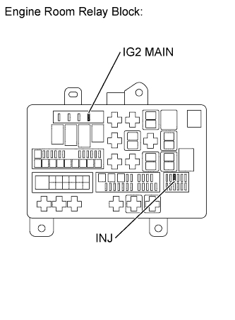
| 4.INSPECT FUSE (INJ, IG2 MAIN) |
-
Remove the INJ fuse and IG2 MAIN fuse from the engine room relay block.
-
Measure the resistance according to the value(s) in the table below.
Standard Resistance:
| Tester Connection |
Condition |
Specified Condition |
| INJ fuse |
Always |
Below 1 ? |
| IG2 MAIN fuse |
Always |
Below 1 ? |
|
|
| CHECK FOR SHORT IN ALL HARNESSES AND CONNECTORS CONNECTED TO FUSE AND REPLACE FUSE |
|
| |
| 5.INSPECT INTEGRATION NO.1 RELAY (IG2) |
-
Inspect the integration relay.
|
|
| REPLACE INTEGRATION NO.1 RELAY |
|
| |
| OK |
|
| |
|
| REPAIR OR REPLACE HARNESS OR CONNECTOR (INTEGRATION RELAY - FUEL INJECTOR ASSEMBLY) |
|
