CHECK HARNESS AND CONNECTOR (INTEGRATION RELAY - BATTERY)
INSPECT INTEGRATION RELAY (EFI RELAY AND IG2 RELAY)
CHECK HARNESS AND CONNECTOR (+B, +B2 AND MREL CIRCUIT)
CHECK HARNESS AND CONNECTOR (ECM - BODY GROUND)
CHECK HARNESS AND CONNECTOR (INTEGRATION RELAY - ECM, INTEGRATION RELAY - BODY GROUND)
CHECK IF VEHICLE IS EQUIPPED WITH ENTRY AND START SYSTEM
CHECK HARNESS AND CONNECTOR (MAIN BODY ECU - ENGINE ROOM RELAY BLOCK)
CHECK ENTRY AND START SYSTEM (POWER SOURCE MODE DOES NOT CHANGE)
CHECK HARNESS AND CONNECTOR (IGNITION SWITCH - ENGINE ROOM RELAY BLOCK)
INSPECT IGNITION SWITCH ASSEMBLY
SFI system - ECM Power Source Circuit
Description
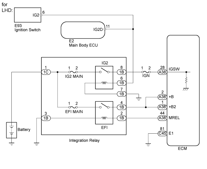
When the ignition switch is turned to ON, battery voltage is applied to the IGSW of the ECM. The output signal from the MREL terminal of the ECM causes a current to flow to the coil, closing the contacts of the integration relay (EFI relay) and supplying power to either terminal +B or +B2 of the ECM.
Wiring diagram

Inspection procedure
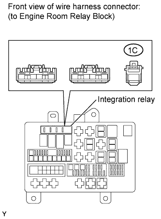
| 1.CHECK HARNESS AND CONNECTOR (INTEGRATION RELAY - BATTERY) |
-
Remove the integration relay from the engine room relay block.
-
Measure the voltage according to the value(s) in the table below.
Standard Voltage:
Tester Connection Condition Specified Condition 1C-1 - Body ground Always 11 to 14 V
|
|
||||
| OK | |
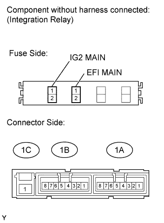
| 2.INSPECT INTEGRATION RELAY (EFI RELAY AND IG2 RELAY) |
-
Remove the integration relay from the engine room relay block.
-
Inspect the EFI MAIN fuse and the IG2 MAIN fuse.
-
Remove the EFI MAIN fuse and IG2 MAIN fuse from the integration relay.
-
Measure the resistance according to the value(s) in the table below.
Standard Resistance:
Tester Connection Condition Specified Condition EFI MAIN fuse Always Below 1 ? IG2 MAIN fuse Always Below 1 ?
-
-
Inspect the EFI relay and the IG2 relay.
-
Measure the resistance according to the value(s) in the table below.
Standard Resistance:
Tester Connection Condition Specified Condition 1C-1 - 1B-4 Battery voltage is not applied to terminals 1B-2 and 1B-3 10 k? or higher Battery voltage is applied to terminals 1B-2 and 1B-3 Below 1 ? 1C-1 - 1B-8 Battery voltage is not applied to terminals 1B-7 and 1B-6 10 k? or higher Battery voltage is applied to terminals 1B-7 and 1B-6 Below 1 ?
-
|
|
||||
| OK | |
| 3.CHECK HARNESS AND CONNECTOR (+B, +B2 AND MREL CIRCUIT) |

-
Check the harness and the connectors between the integration relay and the ECM.
-
Remove the integration relay from the engine room relay block.
-
Disconnect the ECM connector.
-
Measure the resistance according to the value(s) in the table below.
Standard Resistance (Check for Open):
for LHD Tester Connection Condition Specified Condition A38-44 (MREL) - 1B-2 Always Below 1 ? A38-2 (+B) - 1B-4 Always Below 1 ? A38-1 (+B2) - 1B-4 Always Below 1 ? for RHD Tester Connection Condition Specified Condition A52-44 (MREL) - 1B-2 Always Below 1 ? A52-2 (+B) - 1B-4 Always Below 1 ? A52-1 (+B2) - 1B-4 Always Below 1 ? Standard Resistance (Check for Short):
for LHD Tester Connection Condition Specified Condition A38-44 (MREL) or 1B-2 - Body ground Always 10 k? or higher A38-2 (+B) or 1B-4 - Body ground Always 10 k? or higher A38-1 (+B2) or 1B-4 - Body ground Always 10 k? or higher for RHD Tester Connection Condition Specified Condition A52-44 (MREL) or 1B-2 - Body ground Always 10 k? or higher A52-2 (+B) or 1B-4 - Body ground Always 10 k? or higher A52-1 (+B2) or 1B-4 - Body ground Always 10 k? or higher
-
-
Check the harness and connectors between the integration relay and body ground.
-
Measure the resistance according to the value(s) in the table below.
Standard Resistance (Check for Open):
Tester Connection Condition Specified Condition 1B-3 - Body ground Always Below 1 ?
-
|
|
||||
| OK | |
| 4.CHECK HARNESS AND CONNECTOR (ECM - BODY GROUND) |
-
Disconnect the ECM connector.
-
Measure the resistance according to the value(s) in the table below.
Standard Resistance (Check for Open):
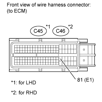
for LHD Tester Connection Condition Specified Condition C45-81 (E1) - Body ground Always Below 1 ? for RHD Tester Connection Condition Specified Condition C46-81 (E1) - Body ground Always Below 1 ?
|
|
||||
| OK | |
| 5.INSPECT ECM (IGSW VOLTAGE) |

-
Disconnect the ECM connector.
-
Measure the voltage according to the value(s) in the table below.
Standard Voltage:
for LHD Tester Connection Switch Condition Specified Condition A38-28 (IGSW) - C45-81 (E1) Ignition switch ON 11 to 14 V for RHD Tester Connection Switch Condition Specified Condition A52-28 (IGSW) - C46-81 (E1) Ignition switch ON 11 to 14 V
|
|
||||
| OK | |
|
| 6.INSPECT FUSE (IGN) |
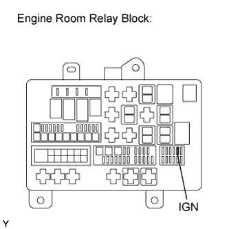
-
Remove the IGN fuse from the engine room relay block.
-
Measure the resistance according to the value(s) in the table below.
Standard Resistance (Check for Open):
Tester Connection Condition Specified Condition IGN fuse Always Below 1 ?
|
|
||||
| OK | |
| 7.CHECK HARNESS AND CONNECTOR (INTEGRATION RELAY - ECM, INTEGRATION RELAY - BODY GROUND) |
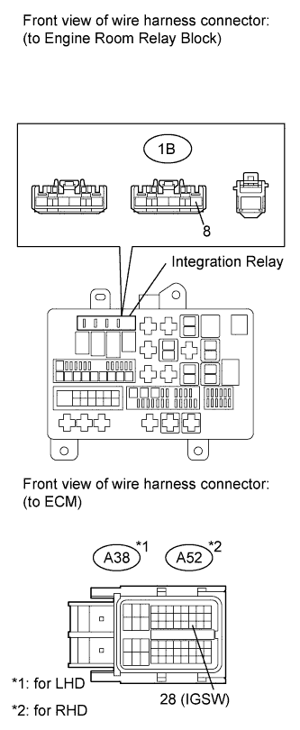
-
Remove the integration relay from the engine room relay block.
-
Disconnect the ECM connector.
-
Measure the resistance according to the value(s) in the table below.
Standard Resistance (Check for Open):
for LHD Tester Connection Condition Specified Condition 1B-8 - A38-28 (IGSW) Always Below 1 ? for RHD Tester Connection Condition Specified Condition 1B-8 - A52-28 (IGSW) Always Below 1 ? Standard Resistance (Check for Short):
for LHD Tester Connection Condition Specified Condition 1B-8 or A38-28 (IGSW) - Body ground Always 10 k? or higher for RHD Tester Connection Condition Specified Condition 1B-8 or A52-28 (IGSW) - Body ground Always 10 k? or higher
|
|
||||
| OK | |
| 8.CHECK IF VEHICLE IS EQUIPPED WITH ENTRY AND START SYSTEM |
| Result | Proceed to |
| w/ Entry and Start System | A |
| w/o Entry and Start System | B |
|
|
||||
| A | |
| 9.CHECK HARNESS AND CONNECTOR (MAIN BODY ECU - ENGINE ROOM RELAY BLOCK) |

-
Remove the integration relay from the engine room relay block.
-
Disconnect the E2 main body ECU connector.
-
Measure the resistance according to the value(s) in the table below.
Standard Resistance (Check for Open):
Tester Connection Condition Specified Condition E2-11 (IG2D) - 1B-6 Always Below 1 ? Standard Resistance (Check for Short):
Tester Connection Condition Specified Condition E2-11 (IG2D) or 1B-6 - Body ground Always 10 k? or higher
|
|
||||
| OK | |
| 10.CHECK ENTRY AND START SYSTEM (POWER SOURCE MODE DOES NOT CHANGE) |
-
Check the entry and start system .
|
|
||||
| OK | |
|
| 11.CHECK HARNESS AND CONNECTOR (IGNITION SWITCH - ENGINE ROOM RELAY BLOCK) |
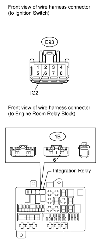
-
Remove the integration relay from the engine room relay block.
-
Disconnect the E93 ignition switch connector.
-
Measure the resistance according to the value(s) in the table below.
Standard Resistance (Check for Open):
Tester Connection Condition Specified Condition E93-6 (IG2) - 1B-6 Always Below 1 ? Standard Resistance (Check for Short):
Tester Connection Condition Specified Condition E93-6 (IG2) or 1B-6 - Body ground Always 10 k? or higher
|
|
||||
| OK | |
| 12.INSPECT IGNITION SWITCH ASSEMBLY |
-
Inspect the ignition switch assembly .
|
|
||||
| OK | |
|