READ VALUE USING INTELLIGENT TESTER (STARTER SIGNAL)
INSPECT PARK/NEUTRAL POSITION SWITCH ASSEMBLY
REPLACE PARK/NEUTRAL POSITION SWITCH ASSEMBLY
READ VALUE USING INTELLIGENT TESTER (STARTER SIGNAL)
CHECK HARNESS AND CONNECTOR (PNP SWITCH OR CLUTCH START SWITCH - STA TERMINAL OF ECM)
CHECK WHETHER DTC OUTPUT RECURS
DTC P0617 Starter Relay Circuit High
Description DTC P0617
While the engine is being cranked, positive battery voltage is applied to terminal STA of the ECM. If the ECM detects the Starter Control (STA) signal while the vehicle is being driven, it determines that there is a malfunction in the STA circuit. The ECM then illuminates the MIL and stores the DTC.
This monitor runs when the vehicle is driven at 20 km/h (12.4 mph) for over 20 seconds.
| DTC Code | DTC Detection Condition | Trouble Area |
| P0617 | When conditions (a), (b) and (c) are met, and a positive (+B) battery voltage of 10.5 V or higher is applied to the ECM for 20 seconds (1 trip detection logic).
|
|
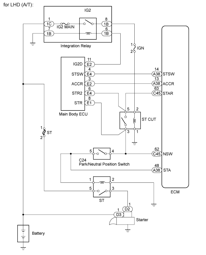
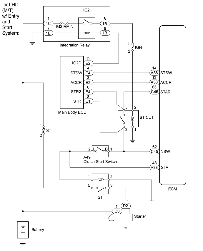
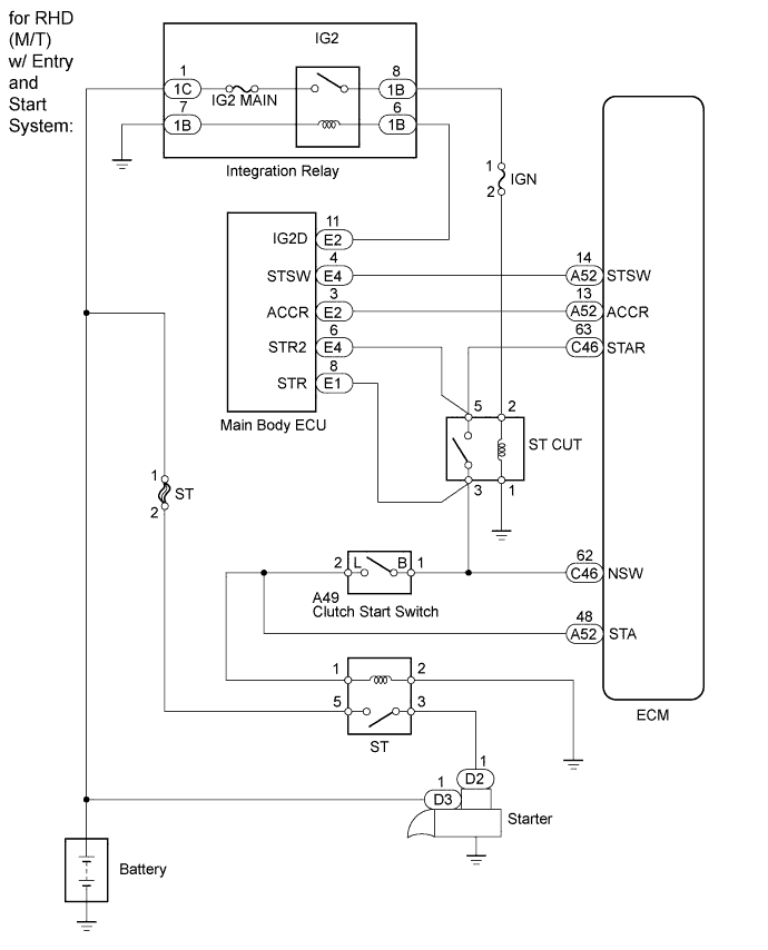
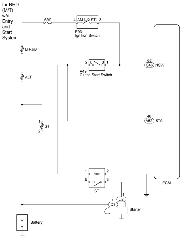
Wiring diagram

Inspection procedure
HINT:
- The following troubleshooting flowchart is based on the premise that the engine is cranked normally. If the engine will not crank, proceed to the Problem Symptoms Table .
- Read freeze frame data using the intelligent tester. Freeze frame data records the engine condition when malfunctions are detected. When troubleshooting, freeze frame data can help determine if the vehicle was moving or stationary, if the engine was warmed up or not, if the air fuel ratio was lean or rich, and other data from the time the malfunction occurred.
| 1.READ VALUE USING INTELLIGENT TESTER (STARTER SIGNAL) |
-
Connect the intelligent tester to the DLC3.
-
Turn the ignition switch to ON and turn the tester on.
-
Enter the following menus: Powertrain / Engine and ECT / Data List / All Data / Starter Signal.
-
Check the value displayed on the tester when the ignition switch is turned to ON and when the engine is started.
Standard:
Ignition Switch Condition Display (Starter Signal) ON OFF Engine is started ON Result Result Proceed to NG (AT) A NG (MT) B OK C
|
|
||||
|
|
||||
| A | |
| 2.INSPECT PARK/NEUTRAL POSITION SWITCH ASSEMBLY |
-
Inspect the park/neutral position switch .
Result Result Proceed to NG A OK B
|
|
||||
| A | |
| 3.REPLACE PARK/NEUTRAL POSITION SWITCH ASSEMBLY |
-
Replace the park/neutral position switch .
|
|
||||
| 4.INSPECT CLUTCH START SWITCH |
-
Check the clutch start switch (for LHD) .
-
Check the clutch start switch (for RHD) .
| Result | Proceed to |
| NG | A |
| OK | B |
|
|
||||
| A | |
| 5.REPLACE CLUTCH START SWITCH |
-
Replace the clutch start switch (for LHD) .
-
Replace the clutch start switch (for RHD) .
| NEXT | |
| 6.READ VALUE USING INTELLIGENT TESTER (STARTER SIGNAL) |
-
Connect the intelligent tester to the DLC3.
-
Turn the ignition switch to ON and turn the tester on.
-
Enter the following menus: Powertrain / Engine and ECT / Data List / All Data / Starter Signal.
-
Check the value displayed on the tester when the ignition switch is turned to ON and when the engine is started.
Standard:
Ignition Switch Condition Display (Starter Signal) ON OFF Engine is started ON Result Result Proceed to NG A OK B
|
|
||||
| A | |
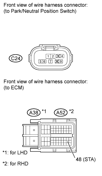
| 7.CHECK HARNESS AND CONNECTOR (PNP SWITCH OR CLUTCH START SWITCH - STA TERMINAL OF ECM) |
-
for Automatic transmission.
-
Disconnect the PNP switch connector.
-
Disconnect the ECM connector.
-
Measure the resistance according to the value(s) in the table below.
Standard Resistance (Check for Open):
for LHD Tester Connection Condition Specified Condition C24-5 - A38-48 (STA) Always Below 1 ? for RHD Tester Connection Condition Specified Condition C24-5 - A52-48 (STA) Always Below 1 ? Standard Resistance (Check for Short):
for LHD Tester Connection Condition Specified Condition C24-5 or A38-48 (STA) - Body ground Always 10 k? or higher for RHD Tester Connection Condition Specified Condition C24-5 or A52-48 (STA) - Body ground Always 10 k? or higher
-
-
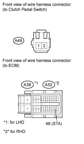
for Manual transmission.
-
Disconnect the clutch pedal switch connector.
-
Disconnect the ECM connector.
-
Measure the resistance according to the value(s) in the table below.
Standard Resistance (Check for Open):
for LHD Tester Connection Condition Specified Condition A49-2 - A38-48 (STA) Always Below 1 ? for RHD Tester Connection Condition Specified Condition A49-2 - A52-48 (STA) Always Below 1 ? Standard Resistance (Check for Short):
for LHD Tester Connection Condition Specified Condition A49-2 or A38-48 (STA) - Body ground Always 10 k? or higher for RHD Tester Connection Condition Specified Condition A49-2 or A52-48 (STA) - Body ground Always 10 k? or higher
-
|
|
||||
| OK | |
| 8.CHECK WHETHER DTC OUTPUT RECURS |
-
Connect the intelligent tester to the DLC3.
-
Turn the ignition switch to ON.
-
Turn the tester on.
-
Clear the DTCs .
-
Drive the vehicle at more than 20 km/h (12.4 mph) for more than 20 seconds.
-
Enter the following menus: Powertrain / Engine and ECT / DTC.
-
Read the DTCs.
Result Result Proceed to No DTC A P0617 (w/ Entry and Start System) B P0617 (w/o Entry and Start System) C
|
|
||||
|
|
||||
| A | |
|