READ DTC OUTPUT (CHECK KNOCK SENSOR CIRCUIT)
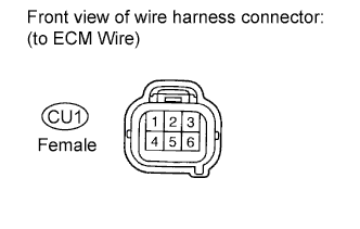
CHECK HARNESS AND CONNECTOR (CONNECTOR - ECM)
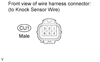
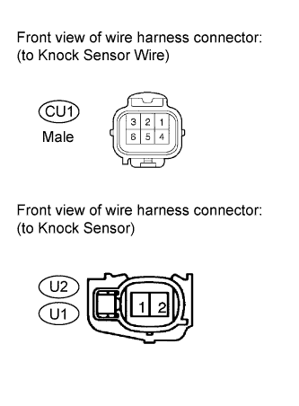
CHECK HARNESS AND CONNECTOR (CONNECTOR - KNOCK SENSOR)
DTC P0327 Knock Sensor 1 Circuit Low Input (Bank 1 or Single Sensor)
DTC P0328 Knock Sensor 1 Circuit High Input (Bank 1 or Single Sensor)
DTC P0332 Knock Sensor 2 Circuit Low Input (Bank 2)
DTC P0333 Knock Sensor 2 Circuit High Input (Bank 2)
Description DTC P0327 P0328 P0332 P0333
Flat type knock sensors (non-resonant type) have structures that can detect vibrations between approximately 6 kHz and 15 kHz.
A knock sensor is fitted onto the engine block to detect engine knocking.
The knock sensor contains a piezoelectric element which generates a voltage when it becomes deformed.
The voltage is generated when the engine block vibrates due to knocking. Any occurrence of engine knocking can be suppressed by delaying the ignition timing.
| DTC Code | DTC Detection Condition | Trouble Area |
| P0327 P0332 | The output voltage of the knock sensor is below 0.5 V (1 trip detection logic). |
|
| P0328 P0333 | The output voltage of the knock sensor is higher than 4.5 V (1 trip detection logic). |
|
HINT:
When any of DTCs P0327, P0328, P0332 and P0333 are stored, the ECM enters fail-safe mode. During fail-safe mode, the ignition timing is delayed to its maximum retardation. Fail-safe mode continues until the ignition switch is turned off.
Reference: Inspection using an oscilloscope
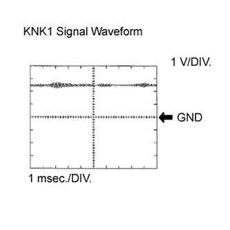
The correct waveform is as shown.
| Item | Content |
| Terminal | KNK1 - EKNK KNK2 - EKN2 |
| Equipment Setting | 1 V/DIV. 1 msec./DIV. |
| Condition | Engine speed maintained at 4000 rpm with warm engine |
Monitor description
If the output voltage transmitted by the knock sensor remains low or high for more than 1 second, the ECM interprets this as a malfunction in the sensor circuit, and stores a DTC.
The monitor for DTCs P0327, P0328, P0332 and P0333 begins to run when 5 seconds have elapsed since the engine was started.
If the malfunction is not repaired successfully, DTC P0327, P0328, P0332 or P0333 is stored 5 seconds after the engine is next started.
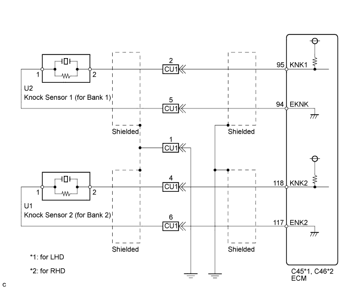
Wiring diagram
Inspection procedure
HINT:
- DTCs P0327 and P0328 are for the bank 1 knock sensor circuit.
- DTCs P0332 and P0333 are for the bank 2 knock sensor circuit.
- Read freeze frame data using the intelligent tester. Freeze frame data records the engine condition when malfunctions are detected. When troubleshooting, freeze frame data can help determine if the vehicle was moving or stationary, if the engine was warmed up or not, if the air fuel ratio was lean or rich, and other data from the time the malfunction occurred.
| 1.READ DTC OUTPUT (CHECK KNOCK SENSOR CIRCUIT) |
-
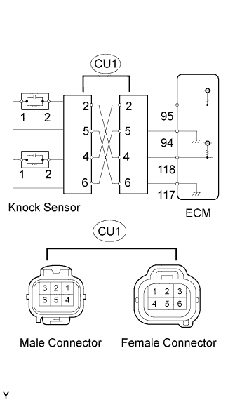
Disconnect the CU1 connector.
-
Using lead wires, connect the connectors as follows:
| Male Connector - Female Connector |
| Terminal 2 - Terminal 4 |
| Terminal 5 - Terminal 6 |
| Terminal 4 - Terminal 2 |
| Terminal 6 - Terminal 5 |
-
Warm up the engine.
-
Run the engine at 3000 rpm for 10 seconds or more.
-
Connect the intelligent tester to the DLC3.
-
Turn the tester on.
-
Enter the following menus: Powertrain / Engine and ECT / Trouble Codes.
-
Read the DTCs.
Result Result Proceed to DTC is same as when vehicle brought in (for example, P0327 and P0328 are output again, or P0332 and P0333 are output again) A DTC is different from when vehicle brought in (for example, P0327 and P0328 are output at first, but then P0332 and P0333 are output, or vice versa) B
|
|
||||
| A | |
| 2.CHECK HARNESS AND CONNECTOR (CONNECTOR - ECM) |
-
Disconnect the CU1 connector.
-
Disconnect the ECM connector.
-
Measure the resistance according to the value(s) in the table below.
Standard Resistance (Check for Open):
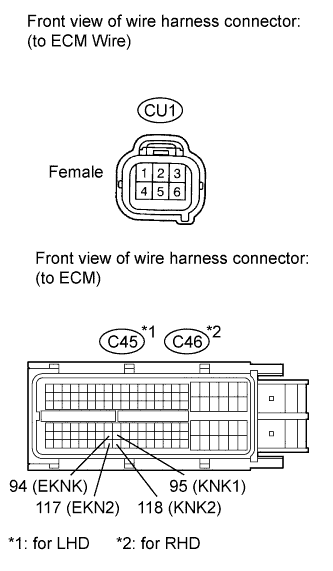
for LHD Tester Connection Condition Specified Condition CU1 female connector 2 - C45-95 (KNK1) Always Below 1 ? CU1 female connector 5 - C45-94 (EKNK) Always Below 1 ? CU1 female connector 4 - C45-118 (KNK2) Always Below 1 ? CU1 female connector 6 - C45-117 (EKN2) Always Below 1 ? for RHD Tester Connection Condition Specified Condition CU1 female connector 2 - C46-95 (KNK1) Always Below 1 ? CU1 female connector 5 - C46-94 (EKNK) Always Below 1 ? CU1 female connector 4 - C46-118 (KNK2) Always Below 1 ? CU1 female connector 6 - C46-117 (EKN2) Always Below 1 ? Standard Resistance (Check for Short):
for LHD Tester Connection Condition Specified Condition CU1 female connector 2 or C45-95 (KNK1) - Body ground Always 10 k? or higher CU1 female connector 5 or C45-94 (EKNK) - Body ground Always 10 k? or higher CU1 female connector 4 or C45-118 (KNK2) - Body ground Always 10 k? or higher CU1 female connector 6 or C45-117 (EKN2) - Body ground Always 10 k? or higher for RHD Tester Connection Condition Specified Condition CU1 female connector 2 or C46-95 (KNK1) - Body ground Always 10 k? or higher CU1 female connector 5 or C46-94 (EKNK) - Body ground Always 10 k? or higher CU1 female connector 4 or C46-118 (KNK2) - Body ground Always 10 k? or higher CU1 female connector 6 or C46-117 (EKN2) - Body ground Always 10 k? or higher
|
|
||||
| OK | |
| 3.INSPECT ECM (VOLTAGE) |
-
Disconnect the CU1 connector.
-
Measure the voltage according to the value(s) in the table below.
Standard Voltage:
Tester Connection Switch Condition Specified Condition CU1 female connector 2 - 5 Ignition switch ON 4.5 to 5.5 V CU1 female connector 4 - 6 Ignition switch ON 4.5 to 5.5 V
|
|
||||
| OK | |
|
| 4.INSPECT KNOCK SENSOR |
-
Disconnect the CU1 connector.
-
Measure the resistance according to the value(s) in the table below.
Standard Resistance:
Tester Connection Condition Specified Condition CU1 male connector 2 - 5 20°C (68°F) 120 to 280 k? CU1 male connector 4 - 6 20°C (68°F) 120 to 280 k?
|
|
||||
| OK | |
|
| 5.CHECK HARNESS AND CONNECTOR (CONNECTOR - KNOCK SENSOR) |
HINT:
- If DTC P0327 or P0328 has changed to P0332 or P0333, check the knock sensor circuit on the right bank side.
- If DTC P0332 or P0333 has changed to P0327 or P0328, check the knock sensor circuit on the left bank side.
-
Disconnect the CU1 connector.
-
Disconnect the knock sensor connectors.
-
Measure the resistance according to the value(s) in the table below.
Standard Resistance (Check for Open):
Tester Connection Condition Specified Condition CU1 male connector 2 - U2-2 Always Below 1 ? CU1 male connector 5 - U2-1 Always Below 1 ? CU1 male connector 4 - U1-2 Always Below 1 ? CU1 male connector 6 - U1-1 Always Below 1 ? Standard Resistance (Check for Short):
Tester Connection Condition Specified Condition CU1 male connector 2 or U2-2 - Body ground Always 10 k? or higher CU1 male connector 5 or U2-1 - Body ground Always 10 k? or higher CU1 male connector 4 or U1-2 - Body ground Always 10 k? or higher CU1 male connector 6 or U1-1 - Body ground Always 10 k? or higher
|
|
||||
| OK | |
|