READ OUTPUT DTC (DTC P0136, P0137, P0138, P0156, P0157 OR P0158)
READ VALUE USING INTELLIGENT TESTER (OUTPUT VOLTAGE OF HEATED OXYGEN SENSOR)
INSPECT HEATED OXYGEN SENSOR (CHECK FOR SHORT)
CHECK HARNESS AND CONNECTOR (CHECK FOR SHORT)
PERFORM ACTIVE TEST USING INTELLIGENT TESTER (INJECTION VOLUME)
READ VALUE USING INTELLIGENT TESTER (OUTPUT VOLTAGE OF HEATED OXYGEN SENSOR)
PERFORM ACTIVE TEST USING INTELLIGENT TESTER (INJECTION VOLUME)
INSPECT HEATED OXYGEN SENSOR (HEATER RESISTANCE)
CHECK HARNESS AND CONNECTOR (HEATED OXYGEN SENSOR - ECM)
PERFORM CONFIRMATION DRIVING PATTERN
CHECK WHETHER DTC OUTPUT RECURS (DTC P0136, P0137, P0138, P0156, P0157 OR P0158)
PERFORM CONFIRMATION DRIVING PATTERN
CHECK WHETHER DTC OUTPUT RECURS (DTC P0136, P0137, P0138, P0156, P0157 OR P0158)
DTC P0136 Oxygen Sensor Circuit Malfunction (Bank 1 Sensor 2)
DTC P0137 Oxygen Sensor Circuit Low Voltage (Bank 1 Sensor 2)
DTC P0138 Oxygen Sensor Circuit High Voltage (Bank 1 Sensor 2)
DTC P0156 Oxygen Sensor Circuit Malfunction (Bank 2 Sensor 2)
DTC P0157 Oxygen Sensor Circuit Low Voltage (Bank 2 Sensor 2)
DTC P0158 Oxygen Sensor Circuit High Voltage (Bank 2 Sensor 2)
Description DTC P0136 P0137 P0138 P0156 P0157 P0158
HINT:
Sensor 2 refers to the sensor mounted behind the three-way catalytic converter and located far from the engine assembly.
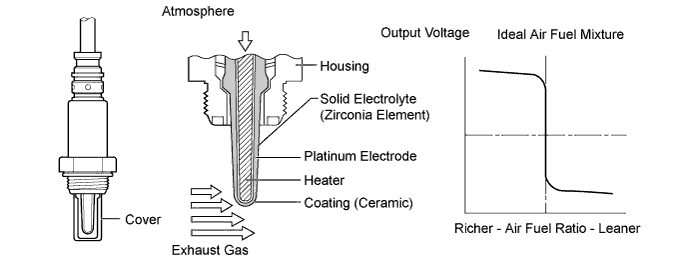
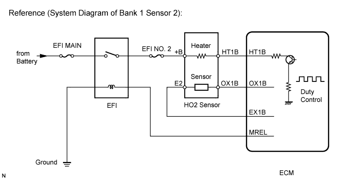
A three-way catalyst converter is used in order to convert the carbon monoxide, hydrocarbons, and nitrogen oxide, into less harmful substances. To allow the three-way catalytic converter to function effectively, it is necessary to keep the air fuel ratio of the engine near the stoichiometric air fuel ratio. For the purpose of helping the ECM to deliver accurate air fuel ratio control, a heated oxygen sensor is used.
The heated oxygen sensor is located behind the three-way catalytic converter, and detects the oxygen concentration in the exhaust gas. Since the sensor is integrated with the heater that heats the sensing portion, it is possible to detect the oxygen concentration even when the intake air volume is low (the exhaust gas temperature is low).
When the air fuel ratio becomes lean, the oxygen concentration in the exhaust gas is rich. The heated oxygen sensor informs the ECM that the post-three way catalytic converter air fuel ratio is lean (low voltage, i.e. below 0.45 V).
Conversely, when the air fuel ratio is richer than the stoichiometric air fuel level, the oxygen concentration in the exhaust gas becomes lean. The heated oxygen sensor informs the ECM that the post-three way catalytic converter air fuel ratio is rich (high voltage, i.e. higher than 0.45 V). The heated oxygen sensor has the property of changing its output voltage drastically when the air fuel ratio is close to the stoichiometric level.
The ECM uses the supplementary information from the heated oxygen sensor to determine whether the air fuel ratio after the three-way catalytic converter is rich or lean, and adjusts the fuel injection time accordingly. Thus, if the heated oxygen sensor is working improperly due to internal malfunctions, the ECM is unable to compensate for deviations in the primary air fuel ratio control.
| DTC Code | DTC Detection Condition | Trouble Area |
| P0136 P0156 |
|
|
| P0137 P0157 |
|
|
| P0138 P0158 |
|
|
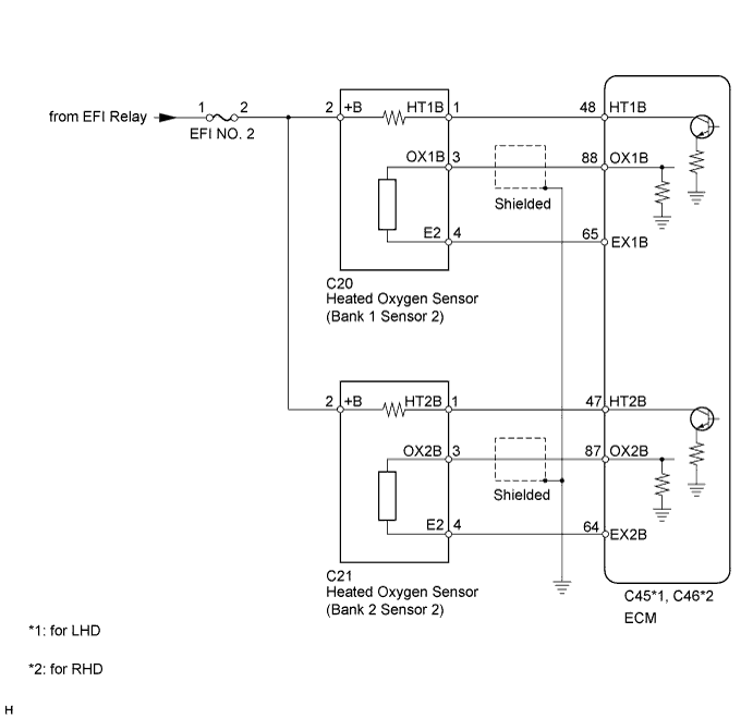
Wiring diagram
Confirmation driving pattern
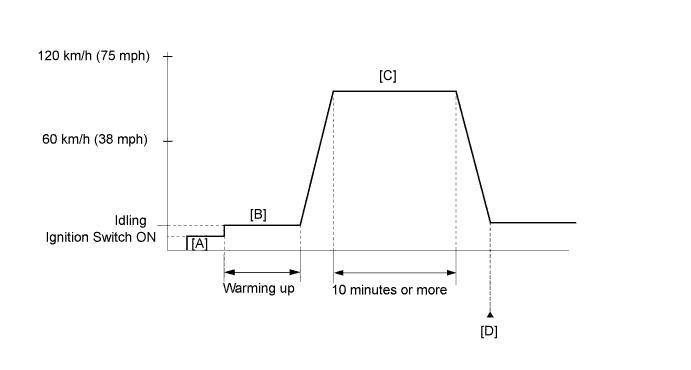
- Connect the intelligent tester to the DLC3 [A].
- Turn the tester on.
- Warm up the engine until the engine coolant temperature is 75°C (167°F) or higher [B].
- Drive the vehicle at 60 to 120 km/h (38 to 75 mph) for at least 10 minutes [C].
- Enter the following menus: Powertrain / Engine / Utility / All Readiness [D].
- Input DTCs: P0136, P0137, P0138, P0156, P0157 and P0158.
- Check that DTC MONITOR is NORMAL. If DTC MONITOR is INCOMPLETE, perform the drive pattern again by accelerating the vehicle and using the second gear to decelerate the vehicle.
Inspection procedure
HINT:
Malfunctioning areas can be identified by performing the Control the Injection Volume for A/F sensor function provided in the Active Test. The Control the Injection Volume for A/F sensor function can help to determine whether the Air Fuel Ratio (A/F) sensor, Heated Oxygen (HO2) sensor and other potential trouble areas are malfunctioning.
The following instructions describe how to conduct the Control the Injection Volume for A/F sensor operation using the intelligent tester.
- Connect the intelligent tester to the DLC3.
- Start the engine and turn the intelligent tester on.
- Warm up the engine at an engine speed of 2500 rpm for approximately 90 seconds.
- Enter the following menus: Powertrain / Engine and ECT / Active Test / Control the Injection Volume for A/F sensor.
- Perform the Active Test operation with the engine idling (press the RIGHT or LEFT button to change the fuel injection volume).
- Monitor the output voltages of the A/F and HO2 sensors (AFS Voltage B1S1 and O2S B1S2, or AFS Voltage B2S1 and O2S B2S2) displayed on the intelligent tester.
HINT:
- The Control the Injection Volume for A/F sensor operation lowers the fuel injection volume by 12.5% or increases the injection volume by 25%.
- Each sensor reacts in accordance with increases and decreases in the fuel injection volume.
| Tester Display (Sensor) | Injection Volume | Status | Voltage |
| AFS Voltage B1S1 or AFS Voltage B2S1 (A/F) | +25% | Rich | Less than 3.1 V |
| AFS Voltage B1S1 or AFS Voltage B2S1 (A/F) | -12.5% | Lean | More than 3.4 V |
| O2S B1S2 or O2S B2S2 (HO2) | +25% | Rich | More than 0.55 V |
| O2S B1S2 or O2S B2S2 (HO2) | -12.5% | Lean | Less than 0.4 V |
NOTICE:
The Air Fuel Ratio (A/F) sensor has an output delay of a few seconds and the Heated Oxygen (HO2) sensor has a maximum output delay of approximately 20 seconds.
| Case | A/F Sensor (Sensor 1) Output Voltage | HO2 Sensor (Sensor 2) Output Voltage | Main Suspected Trouble Area |
| 1 |   |
 |
- |
| 2 | 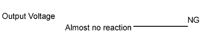 |
|
|
| 3 | |
|
|
| 4 | |
|
|
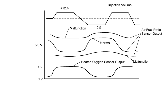
- Following the Control the Injection Volume for A/F sensor procedure enables technicians to check and graph the voltage outputs of both the A/F and HO2 sensors.
- To display the graph, enter the following menus: Powertrain / Engine and ECT / Active Test / Control the Injection Volume for A/F Sensor / A/F Control System / AFS Voltage B1S1 and O2S B1S2 or AFS Voltage B2S1 and O2S B2S2.
HINT:
Read freeze frame data using the intelligent tester. Freeze frame data records the engine condition when malfunctions are detected. When troubleshooting, freeze frame data can help determine if the vehicle was moving or stationary, if the engine was warmed up or not, if the air fuel ratio was lean or rich, and other data from the time the malfunction occurred.
1.READ OUTPUT DTC (DTC P0136, P0137, P0138, P0156, P0157 OR P0158)
-
Connect an intelligent tester to the DLC3.
-
Turn the ignition switch to ON.
-
Turn the tester on.
-
Enter the following menus: Powertrain / Engine and ECT / DTC.
-
Read DTCs.
Result Result Proceed to P0138 or P0158 A P0137 or P0157 B P0136 or P0156 C
|
|
||||
|
|
||||
| A | |
2.READ VALUE USING INTELLIGENT TESTER (OUTPUT VOLTAGE OF HEATED OXYGEN SENSOR)
-
Connect an intelligent tester to the DLC3.
-
Turn the ignition switch to ON.
-
Turn the tester on.
-
Enter the following menus: Powertrain / Engine and ECT / Data List / A/F Control System / O2S B1S2.
-
Allow the engine to idle.
-
Read the heated oxygen sensor output voltage while idling.
Result:
Result Proceed to Higher than 1.0 V A Below 1.0 V B
|
|
||||
| A | |
3.INSPECT HEATED OXYGEN SENSOR (CHECK FOR SHORT)
-
Disconnect the heated oxygen sensor connector.
-
Measure the resistance according to the value(s) in the table below.
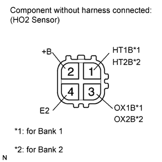
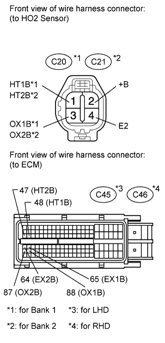
Standard Resistance (Bank 1 Sensor 2):
Tester Connection Condition Specified Condition 2 (+B) - 4 (E2) 20°C (68°F) 10 k? or higher 2 (+B) - 3 (OX1B) Always 10 k? or higher Standard Resistance (Bank 2 Sensor 2):
Tester Connection Condition Specified Condition 2 (+B) - 4 (E2) 20°C (68°F) 10 k? or higher 2 (+B) - 3 (OX2B) Always 10 k? or higher
|
|
||||
| OK | |
4.CHECK HARNESS AND CONNECTOR (CHECK FOR SHORT)
-
Disconnect the ECM connector.
-
Measure the resistance according to the value(s) in the table below.
Standard Resistance:
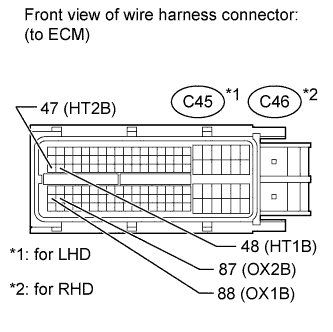
for LHD Tester Connection Condition Specified Condition C45-48 (HT1B) - C45-88 (OX1B) Always 10 k? or higher C45-47 (HT2B) - C45-87 (OX2B) Always 10 k? or higher for RHD Tester Connection Condition Specified Condition C46-48 (HT1B) - C46-88 (OX1B) Always 10 k? or higher C46-47 (HT2B) - C46-87 (OX2B) Always 10 k? or higher
|
|
||||
| OK | |
|
5.PERFORM ACTIVE TEST USING INTELLIGENT TESTER (INJECTION VOLUME)
-
Connect the intelligent tester to the DLC3.
-
Start the engine.
-
Turn the tester on.
-
Warm up the engine.
-
Enter the following menus: Powertrain / Engine / Active Test / Control the Injection Volume.
-
Change the fuel injection volume using the tester, and monitor the voltage output of the air fuel ratio sensor and heated oxygen sensor displayed on the tester.
HINT:
- Change the fuel injection volume within the range of -12% and +12%. The injection volume can be changed in 1% graduations within this range.
- The air fuel ratio sensor is displayed as AFS Voltage B1S1, and the heated oxygen sensor is displayed as O2S B1S2 on the intelligent tester.
Result:
Tester Display (Sensor) Voltage Variation Proceed to AFS Voltage B1S1 (A/F) Alternates between higher than and below 3.3 V OK AFS Voltage B1S1 (A/F) Remains at higher than 3.3 V NG AFS Voltage B1S1 (A/F) Remains at below 3.3 V NG HINT:
A normal heated oxygen sensor voltage (O2S B1S2) reacts in accordance with increases and decreases in fuel injection volumes. When the air fuel ratio sensor voltage remains at either less or higher than 3.3 V despite the heated oxygen sensor indicating a normal reaction, the air fuel ratio sensor is malfunctioning.
|
|
||||
| OK | |
6.CHECK AIR FUEL RATIO SENSOR
HINT:
This air fuel ratio sensor test is to check the air fuel ratio sensor current during the fuel-cut operation. When the sensor is normal, the sensor current will indicate below 3 mA in this test.
-
Connect an intelligent tester to the DLC3.
-
Turn the ignition switch to ON.
-
Turn the tester on.
-
Enter the following menus: Powertrain / Engine and ECT / DTC / Clear.
-
Clear DTCs.
-
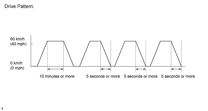
Drive the vehicle by the drive pattern as listed below:
-
Warm up the engine.
-
Drive the vehicle at 60 km/h (40 mph) or more for 10 minutes or more.
-
Stop the vehicle.
-
Accelerate the vehicle to 60 km/h (40 mph) or more and then decelerate for 5 seconds or more. Repeat this process at least 3 times.
-
-
Enter the following menus: Powertrain / Engine and ECT / Data List / A/F Control System / AFS Current B1S1.
-
Read the value of the air fuel ratio sensor current while the fuel-cut operation is performing.
Standard current:
Below 3.0 mA
HINT:
- To measure the air fuel ratio sensor current precisely, perform the fuel-cut operation as long as possible.
- If it is difficult to measure the air fuel ratio sensor current, use the snapshot function of the intelligent tester.
| Result | Proceed to |
| Outside standard range | A |
| Within standard range | B |
|
|
||||
|
|
||||
7.READ VALUE USING INTELLIGENT TESTER (OUTPUT VOLTAGE OF HEATED OXYGEN SENSOR)
-
Connect the intelligent tester to the DLC3.
-
Turn the ignition switch to ON.
-
Turn the tester on.
-
Start the engine.
-
Enter the following menus: Powertrain / Engine and ECT / Data List / A/F Control System / O2S B1S2.
-
After warming up the engine, run the engine at an engine speed of 2500 rpm for 3 minutes.
-
Read the output voltage of the heated oxygen sensor when the engine speed is suddenly increased.
HINT:
Quickly accelerate the engine to 4000 rpm 3 times using the accelerator pedal.
Standard voltage:
Fluctuates between 0.4 V or less and 0.55 V or higher.
|
|
||||
| OK | |
8.PERFORM ACTIVE TEST USING INTELLIGENT TESTER (INJECTION VOLUME)
-
Connect the intelligent tester to the DLC3.
-
Start the engine.
-
Turn the tester on.
-
Warm up the engine.
-
Enter the following menus: Powertrain / Engine / Active Test / Control the Injection Volume.
-
Change the fuel injection volume using the tester, and monitor the voltage output of the air fuel ratio sensor and heated oxygen sensor displayed on the tester.
HINT:
- Change the fuel injection volume within the range of -12% and +12%. The injection volume can be changed in 1% graduations within this range.
- The air fuel ratio sensor is displayed as AFS Voltage B1S1, and the heated oxygen sensor is displayed as O2S B1S2 on the intelligent tester.
Result:
Tester Display (Sensor) Voltage Variation Proceed to AFS Voltage B1S1 (A/F) Alternates between higher than and below 3.3 V OK AFS Voltage B1S1 (A/F) Remains at higher than 3.3 V NG AFS Voltage B1S1 (A/F) Remains at below 3.3 V NG HINT:
A normal heated oxygen sensor voltage (O2S B1S2) reacts in accordance with increases and decreases in fuel injection volumes. When the air fuel ratio sensor voltage remains at either less or higher than 3.3 V despite the heated oxygen sensor indicating a normal reaction, the air fuel ratio sensor is malfunctioning.
|
|
||||
| OK | |
|
9.CHECK FOR EXHAUST GAS LEAK
-
Check for exhaust gas leakage.
OK:
No gas leak.
|
|
||||
| OK | |
10.INSPECT HEATED OXYGEN SENSOR (HEATER RESISTANCE)
-
Disconnect the heated oxygen sensor connector.
-
Measure the resistance according to the value(s) in the table below.
Standard Resistance:
Tester Connection Condition Specified Condition 1 (HT1B) - 2 (+B) 20°C (68°F) 11 to 16 ? 1 (HT1B) - 4 (E2) Always 10 k? or higher
|
|
||||
| OK | |
11.CHECK HARNESS AND CONNECTOR (HEATED OXYGEN SENSOR - ECM)
-
Disconnect the heated oxygen sensor connector.
-
Disconnect the ECM connector.
-
Measure the resistance according to the value(s) in the table below.
Standard Resistance (Check for Open):
for LHD Tester Connection Condition Specified Condition C20-1 (HT1B) - C45-48 (HT1B) Always Below 1 ? C20-3 (OX1B) - C45-88 (OX1B) Always Below 1 ? C20-4 (E2) - C45-65 (EX1B) Always Below 1 ? C21-1 (HT2B) - C45-47 (HT2B) Always Below 1 ? C21-3 (OX2B) - C45-87 (OX2B) Always Below 1 ? C21-4 (E2) - C45-64 (EX2B) Always Below 1 ? for RHD Tester Connection Condition Specified Condition C20-1 (HT1B) - C46-48 (HT1B) Always Below 1 ? C20-3 (OX1B) - C46-88 (OX1B) Always Below 1 ? C20-4 (E2) - C46-65 (EX1B) Always Below 1 ? C21-1 (HT2B) - C46-47 (HT2B) Always Below 1 ? C21-3 (OX2B) - C46-87 (OX2B) Always Below 1 ? C21-4 (E2) - C46-64 (EX2B) Always Below 1 ? Standard Resistance (Check for Short):
for LHD Tester Connection Condition Specified Condition C20-1 (HT1B) or C45-48 (HT1B) - Body ground Always 10 k? or higher C20-3 (OX1B) or C45-88 (OX1B) - Body ground Always 10 k? or higher C20-4 (E2) or C45-65 (EX1B) - Body ground Always 10 k? or higher C21-1 (HT2B) or C45-47 (HT2B) - Body ground Always 10 k? or higher C21-3 (OX2B) or C45-87 (OX2B) - Body ground Always 10 k? or higher C21-4 (E2) or C45-64 (EX2B) - Body ground Always 10 k? or higher for RHD Tester Connection Condition Specified Condition C20-1 (HT1B) or C46-48 (HT1B) - Body ground Always 10 k? or higher C20-3 (OX1B) or C46-88 (OX1B) - Body ground Always 10 k? or higher C20-4 (E2) or C46-65 (EX1B) - Body ground Always 10 k? or higher C21-1 (HT2B) or C46-47 (HT2B) - Body ground Always 10 k? or higher C21-3 (OX2B) or C46-87 (OX2B) - Body ground Always 10 k? or higher C21-4 (E2) or C46-64 (EX2B) - Body ground Always 10 k? or higher
|
|
||||
| OK | |
12.REPLACE HEATED OXYGEN SENSOR
-
Replace the heated oxygen sensor.
| NEXT | |
13.PERFORM CONFIRMATION DRIVING PATTERN
HINT:
Refer to the CONFIRMATION DRIVING PATTERN.
| NEXT | |
14.CHECK WHETHER DTC OUTPUT RECURS (DTC P0136, P0137, P0138, P0156, P0157 OR P0158)
-
Connect an intelligent tester to the DLC3.
-
Turn the ignition switch to ON.
-
Turn the tester on.
-
Enter the following menus: Powertrain / Engine and ECT / Utility / All Readiness.
-
Input DTCs: P0136, P0137, P0138, P0156, P0157 and P0158.
-
Check the DTC monitor is NORMAL. If DTC monitor is INCOMPLETE, perform the drive pattern again by accelerating the vehicle and using the second gear to decelerate the vehicle.
Result Result Proceed to NORMAL (No DTC output) A ABNORMAL (P0136, P0137, P0138, P0156, P0157 or P0158 detected) B
|
|
||||
| A | |
|
15.REPLACE AIR FUEL RATIO SENSOR
-
Replace the air fuel ratio sensor.
| NEXT | |
16.PERFORM CONFIRMATION DRIVING PATTERN
HINT:
Refer to the CONFIRMATION DRIVING PATTERN.
| NEXT | |
17.CHECK WHETHER DTC OUTPUT RECURS (DTC P0136, P0137, P0138, P0156, P0157 OR P0158)
-
Connect an intelligent tester to the DLC3.
-
Turn the ignition switch to ON.
-
Turn the tester on.
-
Enter the following menus: Powertrain / Engine and ECT / Utility / All Readiness.
-
Input DTCs: P0136, P0137, P0138, P0156, P0157 and P0158.
-
Check the DTC monitor is NORMAL. If DTC monitor is INCOMPLETE, perform the drive pattern again by accelerating the vehicle and using the second gear to decelerate the vehicle.
Result Result Proceed to NORMAL (No DTC output) A ABNORMAL (P0136, P0137, P0138, P0156, P0157 or P0158 detected) B
|
|
||||
| A | |
|