PERFORM ACTIVE TEST USING INTELLIGENT TESTER (MOTOR RELAY)
INSPECT SKID CONTROL ECU (+BM TERMINAL)
INSPECT SKID CONTROL ECU (GND TERMINAL)
DTC C1253/53 Pump Motor Relay Malfunction
Description
The motor relay (semiconductor relay) is built into the master cylinder solenoid and drives the pump motor based on a signal from the skid control ECU.
| DTC Code | DTC Detection Condition | Trouble Area |
| C1253/53 | There is a motor system circuit (motor input circuit) malfunction. |
|
Wiring diagram

Inspection procedure
NOTICE:
When replacing the hydraulic brake booster assembly (master cylinder solenoid), perform zero point calibration .
| 1.PERFORM ACTIVE TEST USING INTELLIGENT TESTER (MOTOR RELAY) |
-
Connect the intelligent tester to the DLC3.
-
Turn the ignition switch to ON and turn the intelligent tester on.
-
Start the engine.
-
Enter the following menus: Chassis / ABS/VSC/TRC / Active Test.
ABS/VSC/TRC Tester Display Test Part Control Range Diagnostic Note Motor Relay Motor relay Relay ON/OFF An operation sound of the motor can be heard.
-
Check the operation sound of the motor individually when operating it with the intelligent tester.
OK:
The operation sound of the motor can be heard.
|
|
||||
| OK | |
| 2.RECONFIRM DTC |
-
Clear the DTC .
-
Turn the ignition switch off.
-
Depress the brake pedal more than 20 times.
-
Turn the ignition switch to ON.
-
Wait until the pump motor stops.
-
Depress the brake pedal several times until the pump motor turns on. (Procedure A)
-
Wait until the pump stops. (Procedure B)
-
Repeat the above steps (procedure A and B) 3 more times.
-
Check if the same DTC is output .
HINT:
Reinstall the sensors, connectors, etc. and restore the previous vehicle conditions before rechecking for DTCs.
Result Result Proceed to DTC is not output A DTC is output LHD B RHD C
|
|
||||
|
|
||||
| A | |
|
| 3.INSPECT SKID CONTROL ECU (+BM TERMINAL) |

-
Disconnect the A24 and A25 skid control ECU connectors.
-
Measure the voltage according to the value(s) in the table below.
Standard Voltage:
Tester Connection Condition Specified Condition A24-2 (+BM1) - Body ground Always 11 to 14 V A25-2 (+BM2) - Body ground Always 11 to 14 V
|
|
||||
| OK | |
| 4.INSPECT SKID CONTROL ECU (GND TERMINAL) |
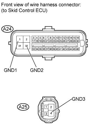
-
Measure the resistance according to the value(s) in the table below.
Standard Resistance:
Tester Connection Condition Specified Condition A24-1 (GND1) - Body ground Always Below 1 ? A24-32 (GND2) - Body ground Always Below 1 ? A25-4 (GND3) - Body ground Always Below 1 ?
|
|
||||
| OK | |
| 5.RECONFIRM DTC |
-
Clear the DTC .
-
Turn the ignition switch off.
-
Depress the brake pedal more than 20 times.
-
Turn the ignition switch to ON.
-
Wait until the pump motor stops.
-
Depress the brake pedal several times until the pump motor turns on. (Procedure A)
-
Wait until the pump stops. (Procedure B)
-
Repeat the above steps (procedure A and B) 3 more times.
-
Check if the same DTC is output .
HINT:
Reinstall the sensors, connectors, etc. and restore the previous vehicle conditions before rechecking for DTCs.
Result Result Proceed to DTC is not output A DTC is output LHD B RHD C
|
|
||||
|
|
||||
| A | |
|