READ VALUE USING INTELLIGENT TESTER (RR/RL SPEED OPEN)
READ VALUE USING INTELLIGENT TESTER (RR/RL WHEEL SPEED, RR/RL WHEEL DIRECTION)
INSPECT REAR SPEED SENSOR INSTALLATION
INSPECT SKID CONTROL SENSOR WIRE
CHECK HARNESS AND CONNECTOR (SKID CONTROL ECU - SKID CONTROL SENSOR WIRE)
INSPECT MASTER CYLINDER SOLENOID (SKID CONTROL ECU OUTPUT VOLTAGE)
DTC C0210/33 Rear Speed Sensor RH Circuit
DTC C0215/34 Rear Speed Sensor LH Circuit
DTC C1238/38 Foreign Object is Attached on Tip of Rear Speed Sensor RH
DTC C1239/39 Foreign Object is Attached on Tip of Rear Speed Sensor LH
Description
The speed sensor detects wheel speed and sends the appropriate signals to the ECU. These signals are used to control the Multi-terrain ABS, EBD and BA systems. This speed sensor contains a sensor IC, which consists of 2 MREs (Magnetic Resistance Element). The speed sensor rotor, which consists of 48 sets of N and S poles that are arranged in a circle, is integrated with the inner race of the hub bearing.
To detect the rotation direction, the output waves are used to determine the relationship of the pulses that are generated by 2 MREs. Upon receiving this signal, the sensor IC outputs a forward or backward wave to the skid control ECU.

| DTC Code | DTC Detection Condition | Trouble Area |
| C0210/33 C0215/34 | When any of the following conditions is detected: 1. At a vehicle speed of 10 km/h (6 mph) or more, the pulses are not input for 1 second. 2. A momentary interruption of the speed sensor signal occurs at least 255 times when switching the ignition switch ON and off. 3. Continuous noise occurs in the speed sensor signals at a vehicle speed of 20 km/h (12 mph) or more. 4. The speed sensor signal circuit is open for 0.12 seconds or more. |
|
| C1238/38 C1239/39 | Noise in the speed sensor signals occurs 75 times or more for 5 seconds when the vehicle speed is 20 km/h (12 mph) or more. |
|
HINT:
- DTC C0210/33 and C1238/38 are for the rear speed sensor RH.
- DTC C0215/34 and C1239/39 are for the rear speed sensor LH.
Wiring diagram

Inspection procedure
NOTICE:
When replacing the master cylinder solenoid, perform zero point calibration .
| 1.READ VALUE USING INTELLIGENT TESTER (RR/RL SPEED OPEN) |
-
Connect the intelligent tester to the DLC3.
-
Turn the ignition switch to ON and turn the intelligent tester on.
-
Enter the following menus: Chassis / ABS/VSC/TRC / Data List.
| Tester Display | Measurement Item/Range | Normal Condition | Diagnostic Note |
| RR Speed Open | Rear speed sensor RH open detection / Error or Normal | Error: Momentary interruption Normal: Normal | - |
| RL Speed Open | Rear speed sensor LH open detection / Error or Normal | Error: Momentary interruption Normal: Normal | - |
-
Check for any momentary interruption in the wire harness and connector corresponding to the DTC .
OK:
There are no momentary interruptions.
HINT:
Perform the above inspection before removing the sensor and connector.
|
|
||||
| OK | |
| 2.READ VALUE USING INTELLIGENT TESTER (RR/RL WHEEL SPEED, RR/RL WHEEL DIRECTION) |
-
Check that there is no difference between the speed value output from the speed sensor displayed on the intelligent tester and the speed value displayed on the speedometer when driving the vehicle.
ABS/VSC/TRC Tester Display Measurement Item/Range Normal Condition Diagnostic Note RR Wheel Speed Rear wheel speed sensor RH reading / min.: 0 km/h (0 mph), max.: 326 km/h (202 mph) Actual wheel speed A similar speed is indicated on the speedometer. RL Wheel Speed Rear wheel speed sensor LH reading / min.: 0 km/h (0 mph), max.: 326 km/h (202 mph) Actual wheel speed A similar speed is indicated on the speedometer. OK:
The speed value output from the speed sensor displayed on the intelligent tester is the same as the actual vehicle speed.
-
Check that the sensor signal conforms to the wheel direction.
ABS/VSC/TRC Tester Display Measurement Item/Range Normal Condition Diagnostic Note RR Wheel Direction Rear wheel direction RH / Forward or Back Forward: Forward Back: Backward - RL Wheel Direction Rear wheel direction LH / Forward or Back Forward: Forward Back: Backward - OK:
The wheel direction is displayed correctly.
|
|
||||
| OK | |
| 3.PERFORM SIGNAL CHECK |
-
Check if test mode (signal check) DTCs are output.
HINT:
Enter the following menus: Chassis / ABS/VSC/TRC / Utility / Signal Check.
Result Result Proceed to Test mode (signal check) DTC is output A Test mode (signal check) DTC is not output B
|
|
||||
| A | |
| 4.INSPECT REAR SPEED SENSOR INSTALLATION |
-
Check the speed sensor installation .
OK:
The installation nut is tightened properly.
There is no clearance between the sensor and rear axle.
NOTICE:
Check the speed sensor signal after replacement .
|
|
||||
| OK | |
| 5.INSPECT SPEED SENSOR TIP |
-
Remove the rear speed sensor .
-
Check the sensor tip.
OK:
No scratches or foreign matter on the sensor tip.
NOTICE:
Check the speed sensor signal after cleaning/replacement .
|
|
||||
| OK | |
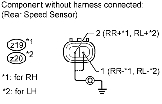
| 6.INSPECT REAR SPEED SENSOR |
-
Install the rear speed sensor.
-
Disconnect the z19 and/or z20 rear speed sensor connector.
-
Measure the resistance according to the value(s) in the table below.
Standard Resistance:
for RH:
Tester Connection Switch Condition Specified Condition z19-2 (RR+) - Body ground Ignition switch off 10 k? or higher z19-1 (RR-) - Body ground Ignition switch off 10 k? or higher for LH:
Tester Connection Switch Condition Specified Condition z20-2 (RL+) - Body ground Ignition switch off 10 k? or higher z20-1 (RL-) - Body ground Ignition switch off 10 k? or higher
|
|
||||
| OK | |
| 7.INSPECT SKID CONTROL SENSOR WIRE |
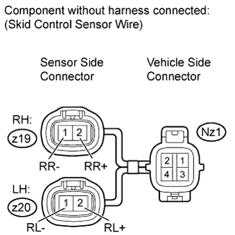
-
Disconnect the z19/z20 and Nz1 skid control sensor wire connectors.
-
Measure the resistance according to the value(s) in the table below.
Standard Resistance:
for RH:
Tester Connection Condition Specified Condition z19-2 (RR+) - Nz1-4 Always Below 1 ? z19-2 (RR+) - Nz1-3 Always 10 k? or higher z19-2 (RR+) - Body ground Always 10 k? or higher z19-1 (RR-) - Nz1-3 Always Below 1 ? z19-1 (RR-) - Nz1-4 Always 10 k? or higher z19-1 (RR-) - Body ground Always 10 k? or higher for LH:
Tester Connection Condition Specified Condition z20-2 (RL+) - Nz1-2 Always Below 1 ? z20-2 (RL+) - Nz1-1 Always 10 k? or higher z20-2 (RL+) - Body ground Always 10 k? or higher z20-1 (RL-) - Nz1-1 Always Below 1 ? z20-1 (RL-) - Nz1-2 Always 10 k? or higher z20-1 (RL-) - Body ground Always 10 k? or higher NOTICE:
Check the speed sensor signal after replacement .
|
|
||||
| OK | |
| 8.CHECK HARNESS AND CONNECTOR (SKID CONTROL ECU - SKID CONTROL SENSOR WIRE) |

-
Disconnect the A24 skid control ECU connector and Nz1 skid control sensor connector.
-
Measure the resistance according to the value(s) in the table below.
Standard Resistance:
for RH:
Tester Connection Condition Specified Condition A24-5 (RR+) - Nz1-4 Always Below 1 ? A24-5 (RR+) - Body ground Always 10 k? or higher A24-19 (RR-) - Nz1-3 Always Below 1 ? A24-19 (RR-) - Body ground Always 10 k? or higher for LH:
Tester Connection Condition Specified Condition A24-20 (RL+) - Nz1-2 Always Below 1 ? A24-20 (RL+) - Body ground Always 10 k? or higher A24-6 (RL-) - Nz1-1 Always Below 1 ? A24-6 (RL-) - Body ground Always 10 k? or higher
|
|
||||
| OK | |
| 9.INSPECT MASTER CYLINDER SOLENOID (SKID CONTROL ECU OUTPUT VOLTAGE) |

-
Reconnect the A24 skid control ECU connector.
-
Measure the voltage according to the value(s) in the table below.
Standard Voltage:
for RH:
Tester Connection Switch Condition Specified Condition Nz1-4 - Body ground Ignition switch ON 7.5 to 12 V for LH:
Tester Connection Switch Condition Specified Condition Nz1-2 - Body ground Ignition switch ON 7.5 to 12 V Result Result Proceed to OK A NG LHD B RHD C
|
|
||||
|
|
||||
| A | |
| 10.RECONFIRM DTC |
-
Clear the DTCs .
-
Drive the vehicle at a speed of approximately 32 km/h (20 mph) or more for 60 seconds or more.
-
Check if the same DTCs are output .
HINT:
Reinstall the sensors, connectors, etc. and restore the previous vehicle conditions before rechecking for DTCs.
Result Result Proceed to DTC is output A DTC is not output (When troubleshooting in accordance with the Diagnostic Trouble Code Chart) B DTC is not output (When troubleshooting in accordance with the Problem Symptoms Table) C
|
|
||||
|
|
||||
| A | |
| 11.REPLACE REAR SPEED SENSOR |
-
Replace the rear speed sensor .
NOTICE:
Check the speed sensor signal after replacement .
| NEXT | |
| 12.RECONFIRM DTC |
-
Clear the DTCs .
-
Drive the vehicle at a speed of approximately 32 km/h (20 mph) or more for 60 seconds or more.
-
Check if the same DTCs are output .
HINT:
Reinstall the sensors, connectors, etc. and restore the previous vehicle conditions before rechecking for DTCs.
Result Result Proceed to DTC is output A DTC is not output B
|
|
||||
| A | |
| 13.INSPECT SPEED SENSOR ROTOR |
-
Remove the rear axle hub and bearing assembly .
-
Check the sensor rotor.
OK:
No scratches, oil, or foreign matter on the rotors.
NOTICE:
Check the speed sensor signal after cleaning/replacement .
Result Result Proceed to NG A OK LHD B RHD C
|
|
||||
|
|
||||
| A | |
|