DESCRIPTION
WIRING DIAGRAM
INSPECTION PROCEDURE
CHECK DTC
INSPECT IF SKID CONTROL ECU CONNECTOR IS SECURELY CONNECTED
INSPECT BATTERY
CHECK CAN COMMUNICATION LINE
CHECK DTC (CAN COMMUNICATION SYSTEM)
CHECK OPERATION OF BRAKE WARNING LIGHT (ACTIVE TEST)
INSPECT SKID CONTROL ECU (IG1 TERMINAL)
INSPECT SKID CONTROL ECU (GND TERMINAL)
INSPECT PARKING BRAKE SWITCH
CHECK HARNESS AND CONNECTOR (SKID CONTROL ECU - PARKING BRAKE SWITCH)
Description
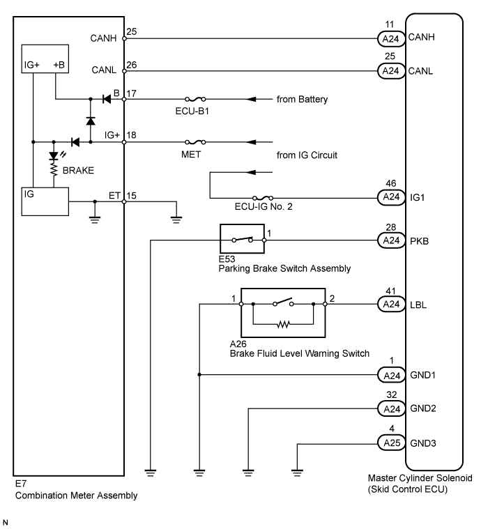
The BRAKE warning light comes on when brake fluid is insufficient, the parking brake is applied or the EBD is defective.
Wiring diagram
Inspection procedure
NOTICE:
When replacing the master cylinder solenoid, perform zero point calibration .
-
Check for DTCs .
Result
| Result |
Proceed to |
| DTC is not output |
A |
| DTC is output |
B |
|
|
| REPAIR CIRCUIT INDICATED BY OUTPUT DTC |
|
| |
| 2.INSPECT IF SKID CONTROL ECU CONNECTOR IS SECURELY CONNECTED |
-
Check the skid control ECU connector connection.
OK:
The connector is securely connected.
|
|
| CONNECT CONNECTOR TO ECU CORRECTLY |
|
| |
-
Check the battery voltage.
Standard voltage:
11 to 14 V
Result
| Result |
Proceed to |
| OK |
A |
| NG |
1GR-FE |
B |
| 2UZ-FE |
C |
| 1VD-FTV |
D |
|
|
| GO TO CHARGING SYSTEM (ON-VEHICLE INSPECTION) |
|
| |
|
|
| GO TO CHARGING SYSTEM (ON-VEHICLE INSPECTION) |
|
| |
|
|
| GO TO CHARGING SYSTEM (ON-VEHICLE INSPECTION) |
|
| |
| 4.CHECK CAN COMMUNICATION LINE |
-
Turn the ignition switch off.
-
Connect the intelligent tester to the DLC3.
-
Turn the ignition switch to ON and the intelligent tester on.
-
Select "Bus Check" from the System Selection Menu screen, and follow the prompts on the screen to inspect the CAN Bus.
OK:
"Bus Check" indicates no malfunctions in CAN communication.
Result
| Result |
Proceed to |
| OK |
A |
| NG |
LHD |
B |
| RHD |
C |
|
|
| GO TO CAN COMMUNICATION SYSTEM (HOW TO PROCEED WITH TROUBLESHOOTING) |
|
| |
|
|
| GO TO CAN COMMUNICATION SYSTEM (HOW TO PROCEED WITH TROUBLESHOOTING) |
|
| |
| 5.CHECK DTC (CAN COMMUNICATION SYSTEM) |
-
Turn the ignition switch off.
-
Connect the intelligent tester to the DLC3.
-
Turn the ignition switch to ON and the intelligent tester on.
-
Check for DTCs (LHD: /RHD: ).
Result
| Result |
Proceed to |
| CAN system DTC is not output |
A |
| CAN system DTC is output |
LHD |
B |
| RHD |
C |
|
|
| GO TO CAN COMMUNICATION SYSTEM (HOW TO PROCEED WITH TROUBLESHOOTING) |
|
| |
|
|
| GO TO CAN COMMUNICATION SYSTEM (HOW TO PROCEED WITH TROUBLESHOOTING) |
|
| |
| 6.CHECK OPERATION OF BRAKE WARNING LIGHT (ACTIVE TEST) |
-
Turn the ignition switch off.
-
Connect the intelligent tester to the DLC3.
-
Turn the ignition switch to ON and the intelligent tester on.
-
Enter the following menus: Body Electrical / Combination Meter / Active Test.
-
Check the condition of the brake warning light by operating the intelligent tester.
Combination Meter
| Tester Display |
Test Part |
Control Range |
Diagnostic Note |
| Indicat. Lamp Brake |
Brake Warning Light |
Warning light ON/OFF |
- |
OK:
The warning light turns on when operating the intelligent tester.
Result
| Result |
Proceed to |
| OK |
A |
| NG |
w/ Multi-information Display |
B |
| w/o Multi-information Display |
C |
|
|
| REPLACE COMBINATION METER ASSEMBLY |
|
| |
|
|
| REPLACE COMBINATION METER ASSEMBLY |
|
| |
| 7.INSPECT SKID CONTROL ECU (IG1 TERMINAL) |
-
Disconnect the A24 skid control ECU connector.
-
Measure the voltage according to the value(s) in the table below.
Standard Voltage:
| Tester Connection |
Switch Condition |
Specified Condition |
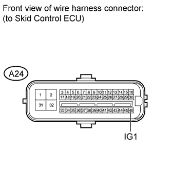
| A24-46 (IG1) - Body ground |
Ignition switch ON |
11 to 14 V |
|
|
| REPAIR OR REPLACE HARNESS OR CONNECTOR |
|
| |
| 8.INSPECT SKID CONTROL ECU (GND TERMINAL) |
-
Disconnect the A24 and A25 skid control ECU connectors.
-
Measure the resistance according to the value(s) in the table below.
Standard Resistance:
| Tester Connection |
Condition |
Specified Condition |
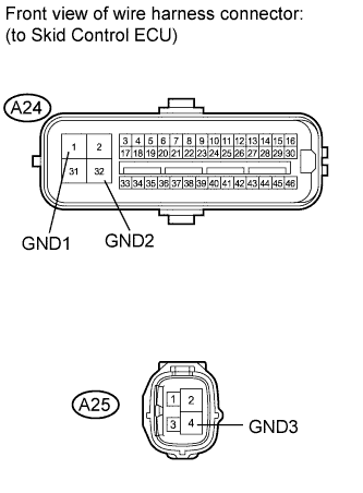
| A24-1 (GND1) - Body ground |
Always |
Below 1 ? |
| A24-32 (GND2) - Body ground |
Always |
Below 1 ? |
| A25-4 (GND3) - Body ground |
Always |
Below 1 ? |
|
|
| REPAIR OR REPLACE HARNESS OR CONNECTOR |
|
| |
| 9.INSPECT PARKING BRAKE SWITCH |

-
Disconnect the E53 parking brake switch connector.
-
Measure the resistance according to the value(s) in the table below.
Standard Resistance:
| Tester Connection |
Switch Condition |
Specified Condition |
| 1 - Body ground |
Parking brake switch on (Switch pin free) |
Below 1 ? |
| 1 - Body ground |
Parking brake switch off (Switch pin pushed in) |
10 k? or higher |
|
|
| REPLACE PARKING BRAKE SWITCH ASSEMBLY |
|
| |
| 10.CHECK HARNESS AND CONNECTOR (SKID CONTROL ECU - PARKING BRAKE SWITCH) |
-
Measure the resistance according to the value(s) in the table below.
Standard Resistance:
| Tester Connection |
Condition |
Specified Condition |
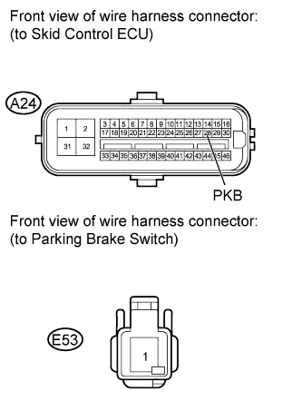
| A24-28 (PKB) - E53-1 |
Always |
Below 1 ? |
| A24-28 (PKB) - Body ground |
Always |
10 k? or higher |
Result
| Result |
Proceed to |
| NG |
A |
| OK |
LHD |
B |
| RHD |
C |
|
|
| REPLACE MASTER CYLINDER SOLENOID |
|
| |
|
|
| REPLACE MASTER CYLINDER SOLENOID |
|
| |
| A |
|
| |
|
| REPAIR OR REPLACE HARNESS OR CONNECTOR |
|